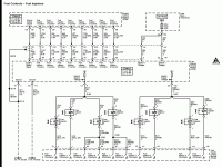
My wheels are turning. Been looking over the wiring diagram and pinout for these FICM's. The control signal from the ECM is eight individual wires, one for each injector to the FICM. If the control signal was a fancy coded logic or CAN/GMLAN then why eight individual lines? This makes me think that the ECM is doing all the heavy lifting on the calculation and just sending the turn on signal down each line for the individual injectors. Maybe something as simple as a square wave, with the duty cycle adjusted for the on duration of the injector.
If this is true then I see no reason why we couldn't make something ourselves to receive this signal and turn of the injectors. I don't know if there is anything that will make the ECM freak out and not run if it doesn't see the FICM on the data bus lines. One would have to get out their scanner and see if there is any injector command after disconnecting the FICM.
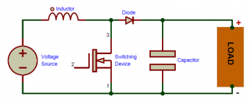
From what I see, it looks like we would just need to build a boost converter for the batteries 12 volts to the injectors 48/96 volts. Then feed that into a bank of capacitors. The signal from the ECM would trigger some mosfets that would discharge the capacitors into the appropriate injector.
Chop out and disregard the proprietary monitoring circuits and code reporting chips and just whittle it down to a basic injector driver.
We would need someone who has a scope and an LLY or LB7 to measure the control signal from the ECM to see what it looks like. This looks like something that would be right up Fingers alley.


