What area are you in up there?I used to years ago before my family moved up from LA
LLY FICM
- Thread starter PureHybrid
- Start date
You are using an out of date browser. It may not display this or other websites correctly.
You should upgrade or use an alternative browser.
You should upgrade or use an alternative browser.
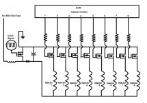
I'll have to take a look at the FICM to see where those extra wires for 6 & 7 go. But I only counted 8 driver mosfets that where connected to the injectors. Is it possible the larger wires where the injector supply voltage?
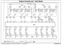
Anything is possible, but I was sure they weren't. I was using a connector pinout from Mitchell, where's that diagram from? Mitchell claims all the connector end views and pinouts are from GM
Folsom. Near Sacramento areaWhat area are you in up there?
Diagram is right from the 2003 and beyond electrical pdf. GM upfitter.com. so truly from GM. Not sure why people go to alldata or others for wiring when GM provides it all free.Anything is possible, but I was sure they weren't. I was using a connector pinout from Mitchell, where's that diagram from? Mitchell claims all the connector end views and pinouts are from GM
Don't think I have been much past Sacramento ever. I rarely go past SanFransico and thats mostly been for work.Folsom. Near Sacramento area
no problem. someone's got to have what we need.Don't think I have been much past Sacramento ever. I rarely go past SanFransico and thats mostly been for work.
I do... I have a SnapOn Verus too. Has a 4 Chanel lab scope on it. I just don't hardly use it any more an not sure what your trying to measure. But I would gladly make my self and truck available. I am sure I can talk my buddy into borrowing his as well if you wanted to verify on more than 1 truck. If I had an extra room I would offer it up as well. Best I could do is probably cash in my hotel points as I never use them anyway...no problem. someone's got to have what we need.
Tap into one of the ECM injector control lines and see what the signal looks like. Preferably under different driving conditions to see if there os any changes. You only need to tap into one line as I'm sure they will all be identical. Also measure the current on the two 12v supply lines to the FICMI do... I have a SnapOn Verus too. Has a 4 Chanel lab scope on it. I just don't hardly use it any more an not sure what your trying to measure. But I would gladly make my self and truck available. I am sure I can talk my buddy into borrowing his as well if you wanted to verify on more than 1 truck. If I had an extra room I would offer it up as well. Best I could do is probably cash in my hotel points as I never use them anyway...
Tell me what pinsTap into one of the ECM injector control lines and see what the signal looks like. Preferably under different driving conditions to see if there os any changes. You only need to tap into one line as I'm sure they will all be identical. Also measure the current on the two 12v supply lines to the FICM
Yeah, GM seems to switch back and forth with the namingNever herd it called an EDU before.
Been looking at some driver circuits. I think those two injectors that have an extra "control" line attached are for current sense. It's used to sense the current on one injector on each bank so the FICM can make minor adjustments to the control voltage if needed. The LM1949 injector driver circuit has one so it can correctly drop the current after the initial opening.
Attachments
Diagram is right from the 2003 and beyond electrical pdf. GM upfitter.com. so truly from GM. Not sure why people go to alldata or others for wiring when GM provides it all free.
I have access to Mitchell for free too, so it didn't really matter. But I'll compare when I get a chance to see if there is a difference.
From what I saw, both the power supply wires from the FICM run back to the fuse box and are actually spliced into the same spade on that 25a fuse.
If the FICM really does drop voltage after the injector opens, I wonder if the later models that are controlled by the ECM do this, and if it's really necessary with how short of time they are on? I imagine you could build a board to withstand constant power
There's another reason to drop the current once the injector is open. It lowers the strength of the magnetic field so when it turns off the weaker field will collapse quicker and shorten the delay making the on off time for the injector more accurate.I have access to Mitchell for free too, so it didn't really matter. But I'll compare when I get a chance to see if there is a difference.
From what I saw, both the power supply wires from the FICM run back to the fuse box and are actually spliced into the same spade on that 25a fuse.
If the FICM really does drop voltage after the injector opens, I wonder if the later models that are controlled by the ECM do this, and if it's really necessary with how short of time they are on? I imagine you could build a board to withstand constant power
But a flyback diode might be good enough to dump the voltage spikes when the injector is turning off and help dissipate the energy. Even if not, the use of an LM1949 chip on each injector circuit doesn't look like a bad idea
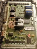
Almost done with this FICM repair. Did some carful removal of the charred board and traces. Jumped out the burned pathways. And soldered in some new 50 volt capacitors (old ones were only rated to 14 volts). I also moved the other capacitors directly off the board to limit the chances of them taking out the board should they blow. Conformal coating also applied to keep any leaking electrolyte or moisture off the board and causing damage
I don't have any way of testing it so I will have to send it back to Purehybrid to put in his truck and see if it works. There is a chance that the arcing could have fried one of the chips or another electrical component. The mosfets looked good with the meter but I have no way to test the processors on these things.
Testing with my multimeter shows no shorts or low resistance on the power to ground Pins. Crossing my fingers


