LLY FICM
- Thread starter PureHybrid
- Start date
You are using an out of date browser. It may not display this or other websites correctly.
You should upgrade or use an alternative browser.
You should upgrade or use an alternative browser.
From what I've gathered on the internet. It seems most vehicles will use a PWM signal to drive the injector controller module. The duty cycle is the duration of the PW. If it's the same for the Duramax then that is good. The LM1949 chip can accept PWM and translate that to injector on time. I just hope the engine speed signal, and the data serial buss are not needed for it to workSeeing the notification for this thread just reminded me that I forgot about doing this...
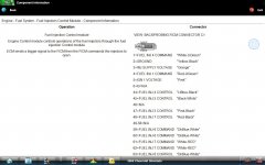
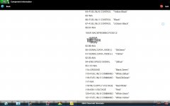
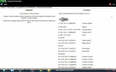
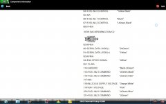
So I just crossed referenced the pinout for both the LB7 and LLY FICMs. They are identical. Anyone ever tried plugging in an LB7 FICM into an LLY to see if it will run?
Edit, thos may have answered my question

Edit, thos may have answered my question

Last edited:
If the communication is different between them, how much does that complicate things when trying come up with an alternative? What would have to be different internally for it to not even try to fire?
If the ecm sent a pw signal while mine was toasted and no comms, I wonder if you could just cut the comm line while trying to run the lb7 ficm so the ecm didn't know what was there
If the ecm sent a pw signal while mine was toasted and no comms, I wonder if you could just cut the comm line while trying to run the lb7 ficm so the ecm didn't know what was there
That's what I'm thinking. Does the ECM even need to know the FICM is there? Doesn't the ECM quarry the com lines when powered up to see what's connected? So if you where to disconnect the FICM communication wires and power cycle the vehicle by disconnecting the batteries. Then the ECM wouldn't even throw any codes for a missing FICM. Hopefully it still sends out the injector trigger signal with "no FICM attached"If the communication is different between them, how much does that complicate things when trying come up with an alternative? What would have to be different internally for it to not even try to fire?
If the ecm sent a pw signal while mine was toasted and no comms, I wonder if you could just cut the comm line while trying to run the lb7 ficm so the ecm didn't know what was there
If it works this way then I'd think that the LB7 one would work on the LLY
Yes, the ECM sends out the "are you there?" signal to all the modules on startup. I miss the days of simple B+ and G- wiring.
Is the comm difference a wiring issue or a language issue?
Is the comm difference a wiring issue or a language issue?
The comms for both are labeled "J1939" with low on pin J2-90 and high for J2-91Yes, the ECM sends out the "are you there?" signal to all the modules on startup. I miss the days of simple B+ and G- wiring.
Is the comm difference a wiring issue or a language issue?
Because of this I assume it's a different language. Or maybe dialect
I'm pretty sure it's 2x 120 ohms. One on each end for a sum of 60 ohms on both the LB7 and the LLYWhat is the difference in resistance on the data bus between the two?
All I can add to the discussion is I can confirm an LB7 FICM will not plug and play on an LLY. Like you, I verified pinouts are the same between them when I had an LLY come in with a bad FICM because I had a good used LB7 FICM laying around and wanted to see if it would work. I didn't try anything tricky to get it going, but it wouldn't run just plugging it in.
Since Im no tech, how does one read the J1939 signal? Could one modify it if they are different between the models?
If GM is truly using the J1939 standard then there is two possibilities that I can think of that might be the reason for the incompatibly between the LLY and LB7. The first is possibly that the data or serial codes, etc are different even though they are transmitted via the same coding. This could be difficult to translate and make work if the ECM is expecting one message and getting something else. The other is the speed. I think at the time there was a 250 kbit and 500 kbit setups. This should be easy to convertSince Im no tech, how does one read the J1939 signal? Could one modify it if they are different between the models?
01-05 is 250k, 06+ GM went to high speed CAN and kept the same J1939 but went to 500k. I had looked into this when I was going to run my PCS-2800 with direct CAN connection. Ben Tyler stated he had done it a few years back in an old post so I thought it was worth the attempt, never attempted it tho.If GM is truly using the J1939 standard then there is two possibilities that I can think of that might be the reason for the incompatibly between the LLY and LB7. The first is possibly that the data or serial codes, etc are different even though they are transmitted via the same coding. This could be difficult to translate and make work if the ECM is expecting one message and getting something else. The other is the speed. I think at the time there was a 250 kbit and 500 kbit setups. This should be easy to convert
So you want me to tap into the Injector 1 Control line ( Not the Command line) to see what kind of a signal we are getting at Idle and under load.Tap into one of the ECM injector control lines and see what the signal looks like. Preferably under different driving conditions to see if there os any changes. You only need to tap into one line as I'm sure they will all be identical. Also measure the current on the two 12v supply lines to the FICM
And also measure current on both the 12V Supply lines.
Is that what you are looking for?
Hmm....so both are wired the same and use the same speed for commands. That leaves only one thing to check....whats actually being "said".
I think I translated the message to English...Hmm....so both are wired the same and use the same speed for commands. That leaves only one thing to check....whats actually being "said".
Stupid Ford, Lets Brake a Crank, Stupid Ford, Stupid Ford, Filthy Cummins, Stupid Ford, Filthy Cummins, Stupid Ford....
Any one of the lines from the ECM to the FICMSo you want me to tap into the Injector 1 Control line ( Not the Command line) to see what kind of a signal we are getting at Idle and under load.
And also measure current on both the 12V Supply lines.
Is that what you are looking for?
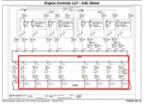
And yes, current on the 12v supply lines. Minimally current through the 25 amp fuse. You may be able to measure the voltage drop across the fuse to calculate the rough current being drawn. That's if you don't want to cut any wires, which is understandable
I should be able to back probe the signal wires at the connector. For the current, don't I need an AMP clamp? I believe I have one of the revised Amp Clamps for the lower Voltage. I need to dig it up any way...Any one of the lines from the ECM to the FICM
View attachment 115485
And yes, current on the 12v supply lines. Minimally current through the 25 amp fuse. You may be able to measure the voltage drop across the fuse to calculate the rough current being drawn. That's if you don't want to cut any wires, which is understandable


