LLY Ficm

kidturbo

Piston Tester
Jul 21, 2010
2,537
1,366
113
Somewhere On The Ohio
www.marinemods.us
Also, what would happen if one of the teeth where bent, damaged or dirty and the sensor has trouble picking it up. Say it misses that tooth will the following injections be retarded by 6° (360/60) until it resets at the -3 gap? I wonder how that would effect the balance rates. It would think the engine slowed down by that one skipped tooth, then inject more fuel to speed it up only to have it over speed on the next. Plus the -6° injection.

Or does it not rely only on counting the teeth each and every time? More like a clock for the ECM to reference and missing pulses are calculated?
Soon as our replacement lb7 ecm shows up, I can produce such errors in my crank ring code, and we shall know. Just a 1 to 0 and a tooth be gone..

As mentioned above, we have 2 crank signals to monitor. 1 in another out. Who's to say they ain't fudging output line version. We've never logged that completely.

Sent from my SM-S901U using Tapatalk
 

2004LB7

Well-known member
Dec 15, 2010
6,970
2,137
113
Norcal
Soon as our replacement lb7 ecm shows up, I can produce such errors in my crank ring code, and we shall know. Just a 1 to 0 and a tooth be gone..

As mentioned above, we have 2 crank signals to monitor. 1 in another out. Who's to say they ain't fudging output line version. We've never logged that completely.

Sent from my SM-S901U using Tapatalk
For the FICM, it only cares about the replicated one. There is no other crank. So are you just seeing if that one is offset from the one provided by the sensor? That could be helpful in determining the start of injection for our FUCM programming
 

kidturbo

Piston Tester
Jul 21, 2010
2,537
1,366
113
Somewhere On The Ohio
www.marinemods.us
Exactly. Where is our delay, and possible compensation, if any, being managed? I've only verified the two pins marked Crank Signal on LB7 ECM are not directly connected together. Could be a simple diode blocking continuity tester. Yet we have 2 matching pattern crank signals available on every engine. And fair reason to believe some engineer may have decided to offset the firing order by 90deg, somehow in this system. I've never looked for such offsets on a LMM, because we don't have access to those 8 control wires. So figure we should verify all the hard components signal so we know exactly where each cylnder is on our magic wheels.


  • Like
Reactions: 2004LB7

kidturbo

Piston Tester
Jul 21, 2010
2,537
1,366
113
Somewhere On The Ohio
www.marinemods.us
Ok who has cad skills and can draw up our 2 simple rector rings? Hate to ask @Cougar281 to scan us some wheel copies I can import into software for demonstration purposes...

Actually figured I would give DALL-2 OpenAI a shot, after seeing all the cool pictures it's dawn up lately.. But for simple task lke draw a 60 tooth reluctor wheel, with 3 teeth removed, it's, fair at best.... Here is what I got by asking..
DALL·E 2023-09-25 21.20.31 - Draw a 3 diameter reluctor ring wheel, 2 center hole, and 60 even...png

Gave it a picture of the cam wheel to start with, thinking that might help.. Ask for a simple outline of this wheel pictured, and it just went all AI mid-evil on it at photoshop level. Like in metal shop with a torch and hammer days.. This first one with square hole I did appreciate.. LOL

DALL·E 2023-09-25 21.21.17.png

DALL·E 2023-09-25 21.19.38.png


Yep I now feel we should all fear AI taking over...
 

1FastBrick

Well-known member
Dec 1, 2016
2,539
1,068
113
Junkyard
Jason, Make one of those pigtails and I will Piggyback my scope. I don't need it that long. Like 1 foot or less. Or...

Tell me how much all the connectors are and I can wire you the money. Then you can send me the crap and I will make my own version.
 

1FastBrick

Well-known member
Dec 1, 2016
2,539
1,068
113
Junkyard
I can't get a clean picture online. If you would have said something earlier I could have brought mine home and If I couldn't do it, i think I have a customer with a light table and a 3d laser scanner that might be able to plot it in cad.
 
  • Like
Reactions: kidturbo

kidturbo

Piston Tester
Jul 21, 2010
2,537
1,366
113
Somewhere On The Ohio
www.marinemods.us
I did find my proof of my other emulated Dmax wheel patter, that I'd been running the Benched LMM's with in past. Here is where I emulated crank cam signals, while capturing the 3 injector line pulses.

Knew I had been using a better patern setup before. This from testing Post injection pulse on the LMM. Hey Jason, guess what should be exactly 15 teeth prior to the crank gap?? But I am still going to go count the teeth again on old blue..


LMM-Scope-3-Pulse.jpg
 

2004LB7

Well-known member
Dec 15, 2010
6,970
2,137
113
Norcal
Jason, Make one of those pigtails and I will Piggyback my scope. I don't need it that long. Like 1 foot or less. Or...

Tell me how much all the connectors are and I can wire you the money. Then you can send me the crap and I will make my own version.
I can do that. I have another connector on the way. When it shows we can figure something out. Or i make a better one with bullet connectors in the middle for me and send you this one to modify to your liking
 
  • Like
Reactions: 1FastBrick

kidturbo

Piston Tester
Jul 21, 2010
2,537
1,366
113
Somewhere On The Ohio
www.marinemods.us
Doing some reading on that MegaSquirt link, if I read it correctly, our crank wheel #1 tooth should be the 1st tooth after the gap. With our Cyl #1 TDC normally being exactly 15 teeth after that. But what has me stumped is the 60-3 count used on LB7/LLY is uncommon And our skipped tooth count can be adjusted to match sensor offsets. So normally I would say that 15 teeth / 90deg is our correct offset, if we had a 60-2 wheel count. But while never seriously discussed online, it certainly does make a difference which tooth you knock off of that LBZ wheel. Maybe not much on bone stock performance, but cranked up timing and pulse width, you could be who 6 degrees off the mark if you pull the wrong tooth..

Also Jason, I answered one of your previous questions above by accident last night. I tried to run that LB7 ECM on my latest modified crank cam emulator setup. But after I found the scope capture above, I also found the correct wheel patterns I'd been using on the LMM's. So I copied and pasted that one into the new code. Wouldn't show RPM above 700.. Would just lock out and not show anything for RPM until I stopped and stared the emulated signals.. Then I looked at the capture and noticed, I had forgotten to remove that extra tooth in my code. Made the change, and ECM showed it registered correctly up to 8100RPM.

So can say they won't run above an idle if you add an extra tooth.. Tomorrow once I get this timing alignment perfectly match to a live engine, I can start knocking teeth off that wheel to see how things react.

@1FastBrick bring you scanner home with you tonight. Need your scope expertise for a few minutes.. Will give ya some Skittles.. I'm about done with this bag. Tested the emulated PW times at various RPM's and works great about 1000rpm.. Even added a pilot. Also tested with the reverse voltage on the controls, last pic. Now say it's ready to light this factory FICM..

Crank-Cam-8-Controls-1.jpg

90us main pulse at 1000RPM

Crank-Cam-8-Controls-2.jpg

Reverse Control Voltage Output

Crank-Cam-8-Controls-Inverted.jpg

Next upload is Running Videos. I promise..
 

kidturbo

Piston Tester
Jul 21, 2010
2,537
1,366
113
Somewhere On The Ohio
www.marinemods.us
Could use a capture of actual cam and crank signal wires. Easily identifiable at bail connectors, as are shielded together in a set of 3.

Beginning to think post man has dropped that lb7 ecm along the way. Shows out for delivery, but not this late in the day..

Sent from my SM-S901U using Tapatalk
 

kidturbo

Piston Tester
Jul 21, 2010
2,537
1,366
113
Somewhere On The Ohio
www.marinemods.us
If you need a scan of an LLY crank reluctor, I do have my originally LLY one.....
If ya have one that's not to dirty, a photo copy, along with a known scale object like a quarter, and most CAD tools can directly import as a drawing. And if not too big of deal, that cam wheel also.

Trying to build an exact model of that crank cam notch relationship. Then we can fudge with numbers going forward. If you happen to have both gears also, could just lay everything out and jump directly to using timing marks on the gears. What you may have noticed in your first pictures, those 2 TDC markers on cam wheel are offset to our horizontal line by just a smidgen...


Sent from my SM-S901U using Tapatalk
 

Cougar281

Well-known member
Sep 11, 2006
1,809
253
83
St Louis, MO
If ya have one that's not to dirty, a photo copy, along with a known scale object like a quarter, and most CAD tools can directly import as a drawing. And if not too big of deal, that cam wheel also.

Trying to build an exact model of that crank cam notch relationship. Then we can fudge with numbers going forward. If you happen to have both gears also, could just lay everything out and jump directly to using timing marks on the gears. What you may have noticed in your first pictures, those 2 TDC markers on cam wheel are offset to our horizontal line by just a smidgen...


Sent from my SM-S901U using Tapatalk
Should be doable... let me dig out my scanner and I should be able to have them scanned tomorrow. Speaking of tomorrow, it seems USPS is doing what they do best and not delivering on time :rolleyes:. The ECM either came back to St Louis or never left when they said it did in the first place and is now supposed to be delivered tomorrow.

Edit: Gotta love this nonsense:
1695775739699.png
 
Last edited:
  • Like
Reactions: kidturbo

kidturbo

Piston Tester
Jul 21, 2010
2,537
1,366
113
Somewhere On The Ohio
www.marinemods.us
Earlier it showed me in Columbus out for delivery... That's usually a good sign they don't know where it is.. If they only had an accurate tracking system, like say UPS? My son's diag tracker can tell what each driver ate for lunch 3 days ago, and why my package smells like curry... lol

No biggie, but while on the subject, please check your bench harness pink wire pinout for me. I spent a while on this fuseblock last night and have everything wired up correctly best I can tell. However, there is a PK wire connected to ECM that triggers our main PCM relay. It's still wired up as factory, and I never cut it. Yet unless this ecm somehow uses class2 line to wake up and send power on sig, that pink wire shares a line to our key on power..

It powers up relay and other pinks just fine with it tied in directly to key, and ecm the powers up the FICM relay to. Which one thing I did notice last night was this ecm did seem to be power cycling the ficm relay while I was feeding it a live crank cam signal. Like it was unhappy there was no ficm talking on the canbus or something. Not positive, but it was cycling a relay for some reason. So just wanta be sure we have all the right pins powered up correctly.


Sent from my SM-S901U using Tapatalk
 

Cougar281

Well-known member
Sep 11, 2006
1,809
253
83
St Louis, MO
Earlier it showed me in Columbus out for delivery... That's usually a good sign they don't know where it is.. If they only had an accurate tracking system, like say UPS? My son's diag tracker can tell what each driver ate for lunch 3 days ago, and why my package smells like curry... lol

No biggie, but while on the subject, please check your bench harness pink wire pinout for me. I spent a while on this fuseblock last night and have everything wired up correctly best I can tell. However, there is a PK wire connected to ECM that triggers our main PCM relay. It's still wired up as factory, and I never cut it. Yet unless this ecm somehow uses class2 line to wake up and send power on sig, that pink wire shares a line to our key on power..

It powers up relay and other pinks just fine with it tied in directly to key, and ecm the powers up the FICM relay to. Which one thing I did notice last night was this ecm did seem to be power cycling the ficm relay while I was feeding it a live crank cam signal. Like it was unhappy there was no ficm talking on the canbus or something. Not positive, but it was cycling a relay for some reason. So just wanta be sure we have all the right pins powered up correctly.


Sent from my SM-S901U using Tapatalk
Colors won't do any good with my bench harness... it's put together with random wire pieces that had factory terminals connected and based on schematic pinouts... I can get you ECM schematics or tell you what should be in what position based on the schematics, but looking for a specific color isn't going to work lol.

Sent from my Pixel 7 using Tapatalk
 

kidturbo

Piston Tester
Jul 21, 2010
2,537
1,366
113
Somewhere On The Ohio
www.marinemods.us
Colors won't do any good with my bench harness... it's put together with random wire pieces that had factory terminals connected and based on schematic pinouts... I can get you ECM schematics or tell you what should be in what position based on the schematics, but looking for a specific color isn't going to work lol.

Sent from my Pixel 7 using Tapatalk
Sorry, I'm so used to looking at these factory wires, I just see Batt and Relayed power as colors. Ok here is what I have

C1
  • 01 - BK/WH - 351 - GND
  • 40 - BK/WH - 351 - GND
  • 20 - OG - 440 - Battery Positive
  • 57 - OG - 440 - Battery Positive
  • 19 - PK - 439 - Ingition 1 Voltage - To PCM Relay 1 Control
  • 75 - PK - 1020 - Off/Crank/Run - Not Listed In Fuse Block
C2
  • 01 - BK/WH - 351 - GND
  • 40 - BK/WH - 351 - GND
  • 44 - PK - 339 - Ingition 1 Voltage - Eng4 Fuse
  • 58 - Class 2 Serial
Typically on the LBZ/LMM stuff, all PCM relay controlled "Ignition Voltage" board power related, are pinks. Ya tie those together with the always blue, serial data wakeup wire, and that's your key-on power up on bench or whatever. And in about every GM fuse block I've played with, pinks are typically your relayed powers.

However this one seems to break those rules slightly. And I have Pk Circuit 439 going into relay pin C4 in our fuse block, which is relay control pin for a PK Circuit 339 above, Fuse socket for Ignition 1 Voltage. So 439 from ECM or another missing wire source powers up circit 339 and some other unused here, via relay. But I'm lost as to what 1020 does then? Not in my current pinout list.
 

kidturbo

Piston Tester
Jul 21, 2010
2,537
1,366
113
Somewhere On The Ohio
www.marinemods.us
Ok believe I've answered all of my wiring questions.. Old trusty GM Upfitter comes through again.

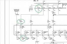
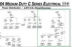
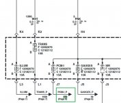
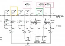
A Medium Duty LB7/ LLY, Circuit 1020 is actually [Key-On] directly powered from the ignition switch. It runs to several nodes, like TCM, and acts like our serial data wake on wire on LBZ/LMM. It starts out life as Circuit 1390, a white wire leaving the ignition switch, then at first connector, becomes Circuit 1020 a PK wire for ever more..

Circuit 439, also a pink wire, comes directly from the ignition switch too, but runs about 3 loops through the fuse block, around the muffler twice, then to a single relay, that when closed controls,,, Circuit 339. Had to edit cause still confused.. lol

Basically, I look to have everything wired up correctly on my bench rig. And my previous assumption stands, that if you hook all the pink wires in a factory harness together, run those to a key-on power, have the battery + and grounds hooked up correctly, any GM ECM should power up correctly on the bench. Pink is key. Small Disclaimer: "The LB7 ECM has one lone pink wire feeding an external fan relay from ECM that doesn't align with anything I just said..."

For those who like to start the day with confusion, please try to following along our GM ignition routing below.
 

Attachments

  • Circuit_1020.jpg
    Circuit_1020.jpg
    110.4 KB · Views: 7
  • Circuit_1020-2.jpg
    Circuit_1020-2.jpg
    134.9 KB · Views: 7
  • Circuit_439-1.jpg
    Circuit_439-1.jpg
    73.9 KB · Views: 7
  • Circuit_439-2.jpg
    Circuit_439-2.jpg
    89.9 KB · Views: 7
Last edited: