well I got to personally see and drive in mainer's twin truck . the sound is awesome and it has really good pull on it for as little tune he has loaded . he did a great job on it . as if i didnt have to save money for a suncoast kit now i need to figure out how to get a set of twins . CONGRATS MAINER
DIY twins/ build thread
- Thread starter mainer
- Start date
You are using an out of date browser. It may not display this or other websites correctly.
You should upgrade or use an alternative browser.
You should upgrade or use an alternative browser.
I am confused as to why you don't want to run the PPE boost valve. The exhaust gets to the second turbo either way. Either it goes through the wastegate or it goes through the turbo into the exhaust. I thought you wanted to get maximum effort out of the exhuast before it goes to turbo #2.
But your saying that you want the wastegate to pop off sooner to help spool turbo 2.
I thought the whole point to twins was to use the most exhaust energy as possible and by bypassing the first turbo, that air is not making power.
But your saying that you want the wastegate to pop off sooner to help spool turbo 2.
I thought the whole point to twins was to use the most exhaust energy as possible and by bypassing the first turbo, that air is not making power.
I am confused as to why you don't want to run the PPE boost valve. The exhaust gets to the second turbo either way. Either it goes through the wastegate or it goes through the turbo into the exhaust. I thought you wanted to get maximum effort out of the exhuast before it goes to turbo #2.
But your saying that you want the wastegate to pop off sooner to help spool turbo 2.
I thought the whole point to twins was to use the most exhaust energy as possible and by bypassing the first turbo, that air is not making power.
You need to look back where twins were explained and read posts more thoroughly.
yep
basically the path is
outside air ---> inlet of big turbo compressor ---> outlet of big compressor ---> inlet of small turbo compressor ---> outlet of small turbo compressor ---> intercooler ---> outlet of intercooler ---> into the engine
then on the exhaust its the opposite
engine exhaust ---> inlet of small turbo turbine ---> outlet of small turbo turbine ---> inlet of big turbo turbine ---> outlet of big turbo turbine ---> downpipe/exhaust pipe
ben
So by allowing the opening of a waste gate you are trying to drive the big turbo to get the intial compression of the air. To get things to spool up together.
Someone explain the 50/50 rule or the 60/40. I barely understand 1 turbo let alone 2 working together.
I guess I don't know anything but what's the idea behind running compound turbo's compared with running true that could be smaller and easier to spool. Are you still dealing with smaller compressor maps?
not that im an expert by any means but let me see if i can explain how i see it . take a 3 in water hose and feed it into a 1 in hose . the 3 in has alot more volume along with pressure . so as it feeds the 1 in it pumps up the pressure . if u took 2 , 1 in hoses and feed one into the other u wouldnt get anymore pressure . if im off base here guys im sorry , maybe someone can put it in another term to help some people understand
So by allowing the opening of a waste gate you are trying to drive the big turbo to get the intial compression of the air. To get things to spool up together.
Someone explain the 50/50 rule or the 60/40. I barely understand 1 turbo let alone 2 working together.
I guess I don't know anything but what's the idea behind running compound turbo's compared with running true that could be smaller and easier to spool. Are you still dealing with smaller compressor maps?
It's more like 50/50. Two compressors in series cannot operate much past that because they are limited by eachother. A small first turbo will limit flow of the larger. That's an the use of huge vnt chargers is being looked at for the small turbo in a twin set.
It's more like 50/50. Two compressors in series cannot operate much past that because they are limited by eachother. A small first turbo will limit flow of the larger. That's an the use of huge vnt chargers is being looked at for the small turbo in a twin set.
waste gate can bring you past 50/50 but i agree with you i dont really see the need to go past 50/50 , i didnt see any gains/loses in drive pressure . only problem i see with the large vnt's is the exhaust side not familer with the sizes availible , not much gain increasing the compressor side above whats curently availible from danville or fleece , exhaust side would bring alot of options on larger bottom chargers . maps are still relavent in a twin setup but not on the total boost # the boost that that turbo was producing by itself would determine the map i am shure it changes a little but dont know how much .
So are you guys saying that their could be an advantage to running a large exhaust wheel on the small charger to allow better flow to the other charger. Or how about a variable exhaust wheel pitch design? Would this allow the exhaust to flow to the other charger more equally.
If I understand this right you guys would ideally want 50% of the exhaust air flow to go to each turbo? If this is the case, why wouldn't you design the up pipes from one side of the engine to go directly to one turbo and the other side of the engine to go to the other turbo? This would "perfectly" split the exhaust air "work" to each of the turbos and then you could individually monitor back pressure to each turbo.
Example drivers side up pipe feeds stock turbo, exhaust is Y'ed in latter. Passenger side up pipe feeds auxilary turbo. Then make new downpipe to Y the to exhaust sides of the turbo together. This "should" spool both turbos together while still compounding them on the intake side.
Tell me if I am wrong.
Last edited:
So are you guys saying that their could be an advantage to running a large exhaust wheel on the small charger to allow better flow to the other charger. Or how about a variable exhaust wheel pitch design? Would this allow the exhaust to flow to the other charger more equally.
If I understand this right you guys would ideally want 50% of the exhaust air flow to go to each turbo? If this is the case, why wouldn't you design the up pipes from one side of the engine to go directly to one turbo and the other side of the engine to go to the other turbo? This would "perfectly" split the exhaust air "work" to each of the turbos and then you could individually monitor back pressure to each turbo.
Example drivers side up pipe feeds stock turbo, exhaust is Y'ed in latter. Passenger side up pipe feeds auxilary turbo. Then make new downpipe to Y the to exhaust sides of the turbo together. This "should" spool both turbos together while still compounding them on the intake side.
Tell me if I am wrong.
You are forgetting that the main reason for compound turbos is you keep very good spool up because you are getting your first 20 psi from the little turbo ( with some coming from the big one of course )and the little turbo also helps spool the large charger so from 0-20 psi you have no draw backs from a larger turbo .
Then once the big turbo is spooled it really delivers the big airflow , the waste gate on the little charger is used to help get it out of the way ( wich happens at a adustable point )and really kick alot of exaust flow to the large charger wich helps keep drive pressure low and avoiding over speeding it.
Bigger exhaust wheels/ A/R's are great except they slow down spoolup and kinda defeats the pupose of going with twins ,so its a give take . Think of it as really adding a big brother to the small turbo it really doesnt do much untill its needed, heat is what determines its need and it also what makes it spool so you can see hows its a ideal setup , and setup this way it works flawless no need to re-design .
Hope that makes sence , and there are parellel twins that each header would feed a turbo but dont have near the benifits of compounds . i am no experts just know what i have learned from my truck .
Last edited:
i was asked if i could provide info for building oil lines so here it is
in total i spent $101 including shipping from jegs, the flanges go for about $40 for the pair and you would need one more push lock fitting.
so figure around $150 for oil lines
part numbers with description are from jegs
Feed line:
799 670520 - Anodized -6AN Male to 14mm x 1.5 Metric Male Adapter
555 100900 - Pro-Flo 200 Series Braided Hose -4 AN 3 length
555 100221 - -6AN Female to -4AN Male Reducer
555 110000 - Straight Max Flow Hose End -4AN
555 110020 - 90 deg Max Flow Swivel Hose End -4AN
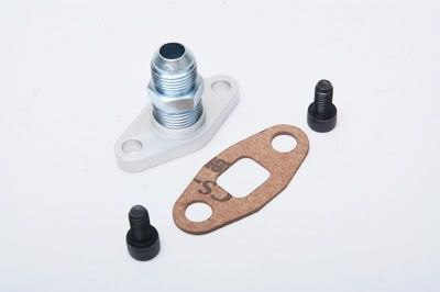
my turbo came with this flange
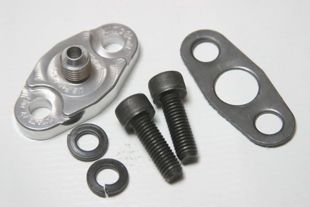
above is everything you need to attach into the port on the block.
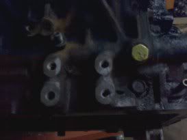
for the oil feed i tapped into the port painted yellow in the following picture, 3ft of the braided line is exactly enough line with where i have my turbo mounted, this is easier than coming up with a banjo type fitting for tie-ing into the stock feed or running 8ft of line from down by the oil filter. (thanks dmaxvaz for the picture)
Drain line:
also will need a 37/64 drill bit, a right angle drill (small) and a 3/8npt tap
555 100128 - Blue 45 deg Flare Fitting 3/8" NPT to 45 deg -10AN flare
555 100053 - Straight Push-Loc Hose End -10AN
555 102030 - Push-Loc Hose Black -10AN 5 ft
i used approx 3.5 ft of the drain line, if i were to do it again i would probably go with braided line for this too but the rubber seems to be working great so far and doesn't destory everything it rubs against.
my turbo came with this flange
in total i spent $101 including shipping from jegs, the flanges go for about $40 for the pair and you would need one more push lock fitting.
so figure around $150 for oil lines
part numbers with description are from jegs
Feed line:
799 670520 - Anodized -6AN Male to 14mm x 1.5 Metric Male Adapter
555 100900 - Pro-Flo 200 Series Braided Hose -4 AN 3 length
555 100221 - -6AN Female to -4AN Male Reducer
555 110000 - Straight Max Flow Hose End -4AN
555 110020 - 90 deg Max Flow Swivel Hose End -4AN
my turbo came with this flange
above is everything you need to attach into the port on the block.
for the oil feed i tapped into the port painted yellow in the following picture, 3ft of the braided line is exactly enough line with where i have my turbo mounted, this is easier than coming up with a banjo type fitting for tie-ing into the stock feed or running 8ft of line from down by the oil filter. (thanks dmaxvaz for the picture)
Drain line:
also will need a 37/64 drill bit, a right angle drill (small) and a 3/8npt tap
555 100128 - Blue 45 deg Flare Fitting 3/8" NPT to 45 deg -10AN flare
555 100053 - Straight Push-Loc Hose End -10AN
555 102030 - Push-Loc Hose Black -10AN 5 ft
i used approx 3.5 ft of the drain line, if i were to do it again i would probably go with braided line for this too but the rubber seems to be working great so far and doesn't destory everything it rubs against.
my turbo came with this flange
Will -10 drain line be enough or is it better to use -12? What did you use to seal your threads going into the pan and block? Just a normal thread sealer?
Last edited:
Will -10 drain line be enough or is it better to use -12? What did you use to seal your threads going into the pan and block? Just a normal thread sealer?
i already answered that to you in your long list of pm's on the dp. do yourself a favor and buy a mpi kit or a industrial injection kit and be done with it! this project seems a little complicated for you.
i already answered that to you in your long list of pm's on the dp. do yourself a favor and buy a mpi kit or a industrial injection kit and be done with it! this project seems a little complicated for you.
i've gotten a somewhat endless set of pm's as well and i thought i covered everything very well in my thread..... maybe i should write a book with step by step instructions and a guide on welding/ grinding/ general fabrication
i've gotten a somewhat endless set of pm's as well and i thought i covered everything very well in my thread..... maybe i should write a book with step by step instructions and a guide on welding/ grinding/ general fabrication
:happy2::hello::coolspot:
i've gotten a somewhat endless set of pm's as well and i thought i covered everything very well in my thread..... maybe i should write a book with step by step instructions and a guide on welding/ grinding/ general fabrication
ya you do that im sure plenty of guys would line up for that one
You dont even know what this is about, so get back to finishing your waterpump/ leak issues and get that 700 hp truck to the track. all that smack talk, and no action:rofl:ya you do that im sure plenty of guys would line up for that one
You dont even know what this is about, so get back to finishing your waterpump/ leak issues and get that 700 hp truck to the track. all that smack talk, and no action:rofl:
:spit:
ya you do that im sure plenty of guys would line up for that one
I would, LOL, Just to mail you a copy :book:
i already answered that to you in your long list of pm's on the dp. do yourself a favor and buy a mpi kit or a industrial injection kit and be done with it! this project seems a little complicated for you.
oke::buttkick::funny:
Last edited: