Cranks
- Thread starter Fingers
- Start date
You are using an out of date browser. It may not display this or other websites correctly.
You should upgrade or use an alternative browser.
You should upgrade or use an alternative browser.
- Status
- Not open for further replies.
Fingers, when I build my motor, you are the man I'm coming too, and if you don't have a cam by then, than EDP gets that ")
I have really enjoyed this thread and all of your research.
I have really enjoyed this thread and all of your research.
To me, that seems more vertical flex than torsional flex. Not at all discounting your findings, but looking at how small #1 main bearing and all the added leverage from the crank snout with the heavy balancer and tension from the belt is what (in my opinion) is the reason it is breaking behind 1&2.
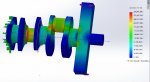
Here is a quick simulation applying a torque to the end of the crank. Note the stress points. Almost impossible to distinguish bend flex from torque flex failure.
It is hard to tell if it was bending or torsional stresses that cause the cranks to snap without looking at the actual failure point itself. Thanks to somebody whose images I poached (it was a while ago so I forgot whose they are...) we have a perfect example that is even well lit by a flash to highlight the beach marks.
The beach marks show that the fracture began at a point almost perfectly centered at the top of the journal. Whether this crack was initiated by an inclusion or by a stress concentrator, further examination of the crank would be required to determine the root cause. However, it appears that the fatigue is from shaft bending, not from torsional stress. If it were a result of torsion, the crack would propagate in the direction of the torsional stress as shown in the 3rd image (and would be opposite to the direction of engine rotation). Here the crack propagation shows that the shaft was bending and resulted in the crankshaft being torn apart little-by-little while in tension.
Without having access to any broken cranks, I can only speculate on the root cause of the breaks. From what I've seen, the cracks typically initiate at the radius at the edge of the journal. Corners are huge stress concentrators, which is why they are given a radius. As a wild guess here (without any cranks to get measurements from) it appears that the radius is too small, which promotes crack development and growth in cranks that may have impurities, inclusions, or other manufacturing defects.
That being said, has anybody broken an internally balanced crank on a duramax?


That being said, has anybody broken an internally balanced crank on a duramax?
Yes, i believe it was stated earlier in this thread or another but it has happened
I really like that people are working on this but the only problem I have with all of it is why bone stock trucks break them and some live over a grand without problems. I honestly hate reading these threads, I am in fear about every time I start my truck now lol
I really like that people are working on this but the only problem I have with all of it is why bone stock trucks break them and some live over a grand without problems. I honestly hate reading these threads, I am in fear about every time I start my truck now lol
The inconsistency of mass production?
It is interesting to note that a NASCAR style flat ground crank would have a twist variation of only 1.00 when using a firing order of 1-8-3-4-7-2-5-6 and be lighter and internally balanced. Shame they generate second order vibrations that most people would find offensive. Much like a 4 cylinder engine does.
Having run those engines on the dyno and at the race track I can tell you those second order vibrations would loosen every nut and bolt in the car. We had to safety wire everything.
Similar problems with the Chevy and Buick V-6 Nascar engines at the time.
It is hard to tell if it was bending or torsional stresses that cause the cranks to snap without looking at the actual failure point itself. Thanks to somebody whose images I poached (it was a while ago so I forgot whose they are...) we have a perfect example that is even well lit by a flash to highlight the beach marks.
.
.
.
.
We've been down this road earlier in the thread. The cumulative stresses on the crank are not enough to induce fatigue failure in of themselves.
The location of the failure initiation is always off center and always in the same direction. As I illustrated with the last FEA for torque, the stress concentration for an applied torque and from bending are in the same place. You can NOT distinguish between them. This is not a shaft being twisted in the classic sense. It is a member non-concentric with the torque being overloaded. (took me a while to realize this)
From where I stand:
Any reduction in the forces on the crank or additional support will reap some reduction in the failure frequency. (Better Dampeners, bigger bearings,...)
However, any addition loads will also increase the frequency of failures. (Blowers, extra CP3s, bad balance,....)
We are just on the edge.
Since the cumulative loads are not enough, the question is where is the extra force coming from? The only mechanism I can come up with is harmonics. Even one undampened force in tune with the cranks torsional harmonic will build to the point of failure.
Changing the firing order does not eliminate the harmonic nature of the crank loading, but it can reduce it's amplitude to a point where the harmonic balancer can absorb the force and prevent the overload. Remember, we are just barely over the line.
Without changing the order, I think a properly designed dampener would reap great benefits too.
The cumulative stresses on the crank are not enough to induce fatigue failure in of themselves.
Given that the fact that the crank failures happen to built and stock trucks seemingly randomly, the crack probably originates from impurities, inclusions, or other manufacturing defects.
The location of the failure initiation is always off center and always in the same direction. As I illustrated with the last FEA for torque, the stress concentration for an applied torque and from bending are in the same place. You can NOT distinguish between them
In your FEA you are correct that you cannot distinguish between the two modes of loading. However, you can distinguish between metal fatigue due to torsion versus bending by analyzing the surface of the failure. The pictures people are posting are all indicating a brittle fracture resulting from cyclic bending.
Since the cumulative loads are not enough, the question is where is the extra force coming from? The only mechanism I can come up with is harmonics. Even one undampened force in tune with the cranks torsional harmonic will build to the point of failure.
Harmonics are probably a large driving force in what is causing the failures. It would be interesting to run a modal analysis on a crankshaft. I'm sure it would provide some interesting answers if somebody threw a crank on a lathe with the flywheel, damper, and bobweights and hit it in several places with a vibrometer while spinning at different speeds.
Anyone looked at the main journal bore of the block at all as well as bearings too?
LBZ mentioned earlier in a reply to my cap-walk post, some blocks have it and some do not. This leads to obvious production inconsistencies both cylinder block (core shift) as well as possible crankshaft production prblems too.
Could the crankshaft counterweight be too thin only employing a certain radius size which I believe the journal width has a responsibilty in this too allowing quick bending failures, IMO yes. Weight savings is great but when something becomes thin/light/too flexable the rigidity is not there which brings in the occurance of drive belts themselves being too tight a root cause ie.
Like you said Fingers, maybe the weight on the snout needs to be more to
has anyone seen a broken crank in a more torsional break
I still believe we need more information involving bearing analysis and main cap walk or no walk. As it is right now, things I believe need to still be considered.
Block main bore alignment
Bearing condition upon failure
Main bearing cap condition
Crankshaft design (edit-counterweight and journal widths)
Auxillary (belts etc)
Not sure if anyone has thought of this in the circle of discussion here, but, what about cylinder wall load and angle of the connecting rod against the crankpin? (rod-stroke ratio)
Last edited:
In your FEA you are correct that you cannot distinguish between the two modes of loading. However, you can distinguish between metal fatigue due to torsion versus bending by analyzing the surface of the failure. The pictures people are posting are all indicating a brittle fracture resulting from cyclic bending.
Go back and look at the actual forces on the rod journal. THEN explain to me how it is being twisted.
Go back and look at the actual forces on the rod journal. THEN explain to me how it is being twisted.
Never once did I say it is being twisted. Bending? Yes. Torsion? No.
Without changing the order, I think a properly designed dampener would reap great benefits too.
Not knowing much about dampener design other than some are counter weighted for proper balance and there are several different dampening materials utilized (fluid, rubber, dynamic shot, etc), what "design" change would you make?
While I don't think the balancer is 100% at fault, there were many threads over the years where guys changed their water pumps (with balancer removal/reinstall), or switched balancers and soon after experienced crank failure. While not a 1 for 1 cause and effect scenario, it was something that always had me wondering (and glad I'm still on original water pump). It leads me to "think" some property of it plays a roll in crank failure (just not smart enough to figure out what it is).
I highly doubt the water pump had anything to do with the failure. They probably did not re install the dampener with the proper torque. After all they are tighter than two frozen squirrel nuts.Not knowing much about dampener design other than some are counter weighted for proper balance and there are several different dampening materials utilized (fluid, rubber, dynamic shot, etc), what "design" change would you make?
While I don't think the balancer is 100% at fault, there were many threads over the years where guys changed their water pumps (with balancer removal/reinstall), or switched balancers and soon after experienced crank failure. While not a 1 for 1 cause and effect scenario, it was something that always had me wondering (and glad I'm still on original water pump). It leads me to "think" some property of it plays a roll in crank failure (just not smart enough to figure out what it is).
Summary to this point
Seems we have some late comers to the discussion. Last summary was in post #111.
Let me do a summary up to this point.
From post #111:
What I have heard here and seems to follow:
Cranks breaking at all power levels.
Breaks mainly on the #1 throw. Along the throw fillet propagating from inside out.
Bearing wear and main walking do not appear to be root causes.
Main alignment does not appear to be the issue.
Things that seem to increase the chance of a broken crank:
heavy loads on the accessory pulley. (Blower, CP3s)
Some Harmonic Balancers
Things that seem to decrease the chance of a broken crank:
Alternate firing order. (which order?)
From there:
Moving on from here:
Need some experimental work done to capture the crank in flex. Should be able to log the signals from the torque converter sensor and the crank sensor to see if their alignment varies. This would not only show crank twist, but could also help determine if there is a base harmonic within the operating range of the engine if the twist changes with RPM.
Seems we have some late comers to the discussion. Last summary was in post #111.
Let me do a summary up to this point.
From post #111:
What I have heard here and seems to follow:
Cranks breaking at all power levels.
Breaks mainly on the #1 throw. Along the throw fillet propagating from inside out.
Bearing wear and main walking do not appear to be root causes.
Main alignment does not appear to be the issue.
Things that seem to increase the chance of a broken crank:
heavy loads on the accessory pulley. (Blower, CP3s)
Some Harmonic Balancers
Things that seem to decrease the chance of a broken crank:
Alternate firing order. (which order?)
From there:
We moved on to explore the actual radial bending loads on the crank from poor balances and found them to be insignificant in of themselves. (1/100 the strength of the crank)
We explored the loads from the combustion process and found the crank to have a Factor of safety in excess of 3 times the max loading. Both in torsion and radial.
Finally, we started looking into the harmonics of the crank and in particular, the firing order and how it affects the loading on the crank. We found the Dmax firing order to be about the most likely to cause rotary deflection of the crank. From that discussion, the 1-5-6-3-4-2-7-8 appears to put a smoother loading on the crank.
Moving on from here:
Need some experimental work done to capture the crank in flex. Should be able to log the signals from the torque converter sensor and the crank sensor to see if their alignment varies. This would not only show crank twist, but could also help determine if there is a base harmonic within the operating range of the engine if the twist changes with RPM.
Never once did I say it is being twisted. Bending? Yes. Torsion? No.
No, you said torque on the crank was not the issue.
What bending are YOU thinking?
Need some experimental work done to capture the crank in flex. Should be able to log the signals from the torque converter sensor and the crank sensor to see if their alignment varies. This would not only show crank twist, but could also help determine if there is a base harmonic within the operating range of the engine if the twist changes with RPM.
Jon do you think the transmission input speed sensor and CKP sensor are accurate enough (especially at higher rpm's) to measure significantly less than 1* difference though??
One thing that might be advantages if you are going to do this is measurement of ISS vs. CKP reference is to swap out your trans speed sensors to 4L80 speed sensors. They are non-directional (unlike the allison oem sensors) and have a stronger magnet in them which might give a better signal...
Ben
EDP Cam
Talk about the EDP cam in another thread please.
Jon
X2
I'm at the machine shop now with my shortblock. Not too late to install an EDP cam!!
This makes me second guess my cam I just bought now... Damnet!!
Since we are on that subject, how much more will these run then the standard ca.?
Talk about the EDP cam in another thread please.
Jon
OK, EDP, don't keep us hangin, how much for a cam with a stock grind?
X2
I'm at the machine shop now with my shortblock. Not too late to install an EDP cam!!
This makes me second guess my cam I just bought now... Damnet!!
This makes me second guess my cam I just bought now... Damnet!!
Since we are on that subject, how much more will these run then the standard ca.?
Last edited by a moderator:
- Status
- Not open for further replies.