we could take some logs with my truck with a Tech2, monitoring the sensors (I have 4l80 sensors) of a before and after the altered firing order. I have David working on matching my current grind to the 1-5-6-3-4-2-7-8 firing order
Cranks
- Thread starter Fingers
- Start date
You are using an out of date browser. It may not display this or other websites correctly.
You should upgrade or use an alternative browser.
You should upgrade or use an alternative browser.
- Status
- Not open for further replies.
we could take some logs with my truck with a Tech2, monitoring the sensors (I have 4l80 sensors) of a before and after the altered firing order. I have David working on matching my current grind to the 1-5-6-3-4-2-7-8 firing order
Im pretty sure any scan tool reading the bus at a lowly 10.4kpbs isnt even going to come anywhere remotely close enough as far as speed and accuracy for what needs to be measured here.............
Tech 2 is worthless for datalogging anyways. Even zoomed in all the way the frame rate is too slow and you cant step frame-by-frame...its only something like 25-frames at a time to read actual data points.
Jon do you think the transmission input speed sensor and CKP sensor are accurate enough (especially at higher rpm's) to measure significantly less than 1* difference though??
One thing that might be advantages if you are going to do this is measurement of ISS vs. CKP reference is to swap out your trans speed sensors to 4L80 speed sensors. They are non-directional (unlike the allison oem sensors) and have a stronger magnet in them which might give a better signal...
Ben
And why wouldn't they be Ben?
I would be looking at the raw signals. Comparing ticks to ticks. Should be able to see phase shift between the two pulse trains.
Im pretty sure any scan tool reading the bus at a lowly 10.4kpbs isnt even going to come anywhere remotely close enough as far as speed and accuracy for what needs to be measured here.............
Tech 2 is worthless for datalogging anyways. Even zoomed in all the way the frame rate is too slow and you cant step frame-by-frame...its only something like 25-frames at a time to read actual data points.
I've never mapped those sensors with one, but couldn't you graph both on top of one another?
No, you said torque on the crank was not the issue.
What bending are YOU thinking?
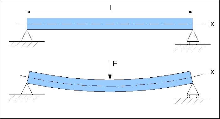
When I say bending, I mean beam bending per the mechanical analysis definition. You will see bending on the crankshaft if you run a modal analysis.
I apologize for misunderstanding earlier.
I ask for clarification here as I may be completely wrong:
It is understood how the cranks fail. What is not understood is why.
If this is true, which is what I understand to be the case per Fingers update, there are several ways to move forward in addition to the data logging.
In order to see how the crankshaft responds to various harmonics (firing impulses from various firing orders, loading scenarios from different snout-driven accessories, and even the "best case" scenario of the crank spinning with bobweights), a form of a modal analysis needs to be done.
- Fingers monitoring the various sensors is one method and should be able to give a rough idea about torsion (about the centerline) in the crankshaft.
- Another method is to analyze the crankshaft analytically or via computer modeling (my preference since analytical methods are rather time consuming). Short of using several very expensive multiphysics programs, this will have to be modeled for several crank angles for each of the firing orders (we should start with stock and then do the one Fingers determined to be less stressful). This won't be too difficult - it will mainly be time consuming.
- The final method (and one I would like to do or see done) is a modal analysis with a laser vibrometer. Ideally this would be done with the crank in the block and a big motor spinning it with the pistons in and heads on, but we'll probably have to settle for a combination of the analytical methods and vibrometer measurements of the crank (with bobweights) spinning at speeds from 0-7000 RPM.
Wouldnt you have to figure out what the force inside each cylinder is during the compression/power stroke, too? How could you simulate that when spinning a crank with only bobweights attached?
Tom, for a harmonic analysis, you only need the mechanical system in question. In this case, the crank with the attached masses. You are looking for the base harmonic. From there, you look for forces and loads that match up to the harmonic. The whole system is desirable, but using bob-weights is a reasonable approximation and is a good start. If the discovered harmonic is anywhere near the operating range of the engine, you dig deeper.
Pinging the crank in the engine is difficult because of all the energy losses at all the connections. An oscillator to drive the oscillations through the frequency scale might work.
Pinging the crank in the engine is difficult because of all the energy losses at all the connections. An oscillator to drive the oscillations through the frequency scale might work.
I apologize for misunderstanding earlier.
I ask for clarification here as I may be completely wrong:
It is understood how the cranks fail. What is not understood is why.
If this is true, which is what I understand to be the case per Fingers update, there are several ways to move forward in addition to the data logging.
In order to see how the crankshaft responds to various harmonics (firing impulses from various firing orders, loading scenarios from different snout-driven accessories, and even the "best case" scenario of the crank spinning with bobweights), a form of a modal analysis needs to be done.
I'll try to get a rough model of the crank made unless somebody on here has a mostly-accurate one (all 4 crank journals and 4 rod journals, accurate-ish spacing and journal diameters). When I get a crank pulled from the truck I'll be able to get a real model of it (yay for laser scanners and faro arms!).
- Fingers monitoring the various sensors is one method and should be able to give a rough idea about torsion (about the centerline) in the crankshaft.
- Another method is to analyze the crankshaft analytically or via computer modeling (my preference since analytical methods are rather time consuming). Short of using several very expensive multiphysics programs, this will have to be modeled for several crank angles for each of the firing orders (we should start with stock and then do the one Fingers determined to be less stressful). This won't be too difficult - it will mainly be time consuming.
- The final method (and one I would like to do or see done) is a modal analysis with a laser vibrometer. Ideally this would be done with the crank in the block and a big motor spinning it with the pistons in and heads on, but we'll probably have to settle for a combination of the analytical methods and vibrometer measurements of the crank (with bobweights) spinning at speeds from 0-7000 RPM.
I currently lack the funds for the simulation package to do the harmonic analysis. Maybe next quarter.
I only have a rough model of the crank. Not accurate enough for a harmonic analysis IMO. The gears, reluctor, and balancer will have to be modeled to complete the mass unit.
I am thinking the belt driven accessories will have to be considered at some point since they add inertia to the system.
Going off of Jon's point of Harmonics, like I stated earlier we believe the harmonics from the stock fire pattern have a hand in the issue. Running the Alter Fire pattern you will notice a complete change in engine tone all the way through the RPM band.
As for accessory driven belts pullies etc. We have a couple trucks running many accessories off the crank with the alter cam and no issues of crank failure 2 years running on both these trucks. One sled pull truck is running 3-4 CP3's Oil system, and Alternator all off the front. Other is a street truck running Oil system, Water System, 80mm Cog Blower Pulley, Two Cp3's, A/C, and Altenator.
As for accessory driven belts pullies etc. We have a couple trucks running many accessories off the crank with the alter cam and no issues of crank failure 2 years running on both these trucks. One sled pull truck is running 3-4 CP3's Oil system, and Alternator all off the front. Other is a street truck running Oil system, Water System, 80mm Cog Blower Pulley, Two Cp3's, A/C, and Altenator.
Last edited by a moderator:
I've been running an alt, firing order cam this year. This cam is from SoCal and the same proven cam design we have been running in Record holding Max'd Out. I'll let Guy tell of the firing order if he'd like, that is not for me to say.
I just wanted to say there are options out there, and that they are working successfully.
I just wanted to say there are options out there, and that they are working successfully.
Kind of an interesting discussion. 
This is nothing new for me, I had done it with Big Block Chevys for years. Heck, Ford never could make up there mind on what firing order they want to use on their small block Windsors. They came from the factory with two or three over the years.
I went ahead and made some cams for testing purposes and have been running them for quite some time. The results have been very promising in A to B testing in engines that have broken cranks and were reassembled without any other changes other than the firing order.
We have run LB7, LLY and LBZ ecms with this firing order and all have been tolerant of it. I have yet to try an LMM, they seem to be a little more picky about things like this, but may prove to be ok.
Bottom line, an excellent discussion …………….and the Dmax community benefits over all from the R&D of many different people.
Guy
Last edited by a moderator:
Does anyone have rough figures on how much stress the accessories actually put on the crank/engine?
How much HP does it take to run the belt-driven accessories such as AC, power steering, and alternator?
What about a second CP3?
Obviously those loads are going to vary based on AC request, how much power steering pressure is needed based on steering/brakes, and what the charge-rate is of the alternator....but what about when all those things are at max?
How much HP does it take to run the water pump?
How much lateral (radial??) "bending" force is placed on the crank snout by the serpentine belt? I guess you could get a rough idea just by measuring how many lbs the serp-belt tensioner spring is???
Ben
We have run LB7, LLY and LBZ ecms with this firing order and all have been tolerant of it. I have yet to try an LMM, they seem to be a little more picky about things like this, but may prove to be ok.
Guy, seeing as the LBZ and LMM ECM's are basically the same EDC-16c controller...what would make an LMM ECM more picky?
I would think any ECM wouldnt even know/care about the difference, as long as it has a proper #1 TDC reference and 180* cam reference.
Why do you think GM/Isuzu chose the firing order they did? I know thats probably a wild card/impossible question that we will never actually know....but Im just curious, given your (and Jon's) knowledge...if you have any educated guesses in how/why GM/Isuzu settled on 1-2-7-8-4-5-6-3??
Guy, seeing as the LBZ and LMM ECM's are basically the same EDC-16c controller...what would make an LMM ECM more picky?
Absolutely nothing!
I would think any ECM wouldnt even know/care about the difference, as long as it has a proper #1 TDC reference and 180* cam reference.
Exaclty
Why do you think GM/Isuzu chose the firing order they did? I know thats probably a wild card/impossible question that we will never actually know....but Im just curious, given your (and Jon's) knowledge...if you have any educated guesses in how/why GM/Isuzu settled on 1-2-7-8-4-5-6-3??
I've talked to high ups on the matter and have had conference calls with a few involved and all said the same thing.... "thats a good question"
Focusing so much on cylinder pressure and our bending action we are forgetting the opposite direction here, the exhaust stroke and flexing with inertia of the reciprocating mass pulling on the crankpin.
Tom, for a harmonic analysis, you only need the mechanical system in question. In this case, the crank with the attached masses. You are looking for the base harmonic. From there, you look for forces and loads that match up to the harmonic. The whole system is desirable, but using bob-weights is a reasonable approximation and is a good start. If the discovered harmonic is anywhere near the operating range of the engine, you dig deeper.
Pinging the crank in the engine is difficult because of all the energy losses at all the connections. An oscillator to drive the oscillations through the frequency scale might work.
Thanks Jon. Pardon my remedial questions, but its not easy following all this when a person doesnt have a mechanical engineering degree. Keep up the good work! :thumb:
TheBac, just keep a dictionary near and remember what your english teacher taught you, analyze sentences and anyone will be fine understanding the basics on any topic.
I highly doubt the water pump had anything to do with the failure. They probably did not re install the dampener with the proper torque. After all they are tighter than two frozen squirrel nuts.
That's what I was stating (the balancer has to be "disturbed" when replacing water pump), not that the water pump had any effect on it.
I've been running an alt, firing order cam this year. This cam is from SoCal and the same proven cam design we have been running in Record holding Max'd Out. I'll let Guy tell of the firing order if he'd like, that is not for me to say.
I just wanted to say there are options out there, and that they are working successfully.
What has to change in the tuning to run an alt fire cam? The "tune" shouldn't have to change, just wondering where firing order is determined... (I have EFI Live but haven't looked at it in over 3 years.)
Edit: Just read Guy's post and it looks like re-wiring injectors is how it's done. While much like me swapping the 4/7 spark plug wires on my BBC with alt fire cam, I would have thought there would be an easier way (without rewiring).
Last edited:
- Status
- Not open for further replies.