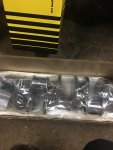
Have you ever thought about relief cutting the big end to let oil escape from between the rods? Since it will be sustained high rpm.
Actually yes. I looked at how several big engine builders do it on high HP gas marine engines. Then I measured that first pair of thinned rods on one of the new Callies cranks. Had about 0.021 clearance between them cut to specs from Jeremy's rod guy. That's right at GM's service limits.
Once we receive the finished cranks there will be plenty more measuring. With this pressurized pin oiling setup, need to consider these implications closer. Have been polling everyone I know running these rods for better data on this setup. Including their designer Curtis H, who explained these drilled bearings I purchased with the rods are all wrong...
Besides being P bearings rather than H, Curtis tells me the drilled hole doesn't belong directly over the hole through center of the rod. Reason for the slot cut shown below, is to allow both crank and rod oiling holes to meet where they align with specific crank angle on the downward stroke. Thus pressurizing the pin only when it's unloaded. Explains that slot..
Also see the tang location after the rods were cut to new journal specs. There isn't much extra meat on these Dmax cranks to begin with. I'd loved to had time to explore a larger main journal dia to increase rod journal overlap as some have suggested. Then your adding some serious meat to that area, more than a mere 0.045 each side by narrowing the rod journal.


