LLY Ficm

kidturbo

Piston Tester
Jul 21, 2010
2,537
1,366
113
Somewhere On The Ohio
www.marinemods.us
Here is where I started down the rabbit hole. The site listing the schematics for sale.


Half way down the page, find couple links to 2 free zip files. Grab those for starters and check em out. They will certainly get ya a few of the chips pinned out. Since all these boards share majority of IC's across platforms.

Probably worth the coin just to buy his copy since searching by each file has produced less than stellar results for me..
 
  • Like
Reactions: 1FastBrick

2004LB7

Well-known member
Dec 15, 2010
6,970
2,137
113
Norcal
Also my thoughts on>
"The NOR gate on the back side of the board. All the control signals rout to this chip. NOR gates work by comparing all of it's inputs and when all are low the it turns on it's output. This partially explains the reason for the signal reversal from the LB7 FICM. Probably using a different signal receiver that needs all to be high to output"

The processor needs to charge the coils on the board to ramp up the voltage. 2 coils, 8 injectors. It can't charge while any injector is firing. Does that sound correct?

We know for certain it's not using CANbus data for anything beyond diagnostics. So that's out. However in a couple video's I've watched, and in some documents I keep seeing statement "Boost Curve". used. At first I thought like Turbo Boost, but now am thinking differently.. Just a thought, I never searched deeper.
Boost curve might be referring to the boost converter part of the circuit that is responsible for making the high voltage used to run the injectors. Not sure on the "curve" part unless it's in reference to the high voltage hit right at the beginning of the injector opening and then a tapering off until the injector is turned off

On the LLY FICM, the boost circuit works by having the N510AB Mosfet turn on and conducting current through the inductor to ground. This charges up the magnetic field of the inductor. When that mosfet turns off the current stops so the magnetic field collapses. This collapsing field induces voltage on the indicator. Because there is no pathway through the mosfet to dump the charge being built up the voltage rises up to the point that it is higher then what is stored in the capacitors. So the current in the inductor will then flow into the caps. A diode keeps the capacitors from discharged back into the inductor or to ground via the mosfet.

This process can occur regardless of the injectors being fired or not. There is a balancing act where the current from the inductor will be lower the higher the voltage is. So the higher it goes the less current you get. So at a point the voltage and current will match what is being drawn by the injectors. And the engineers planned the inductor and capacitors to have enough power to maintain 48 volts even under the heaviest use. To keep the boost circuit from overshooting the voltage when the injectors aren't drawing much, say during idle, the 510 mosfet limits the duty cycle to keep the inductor from charging up the capacitors.

I captured the duty cycle of this on my scope. I'll post it up later. It's in interesting pattern. A large pulse followed by a series of short pulses then ending with another large pulse. Then a pause and repeats over again. I'll need to capture it during some higher loads to see what it does to maintain the proper voltage

I suspect that on the LB7 FICM the strategy is a little different being that there is no inductor on the board. Maybe it uses the injectors as the injectors to change the capacitors? I need to get my hands on one to trace it all out and see what they did
 

2004LB7

Well-known member
Dec 15, 2010
6,970
2,137
113
Norcal
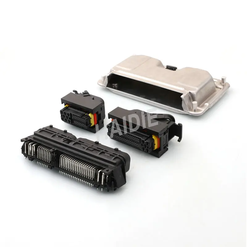
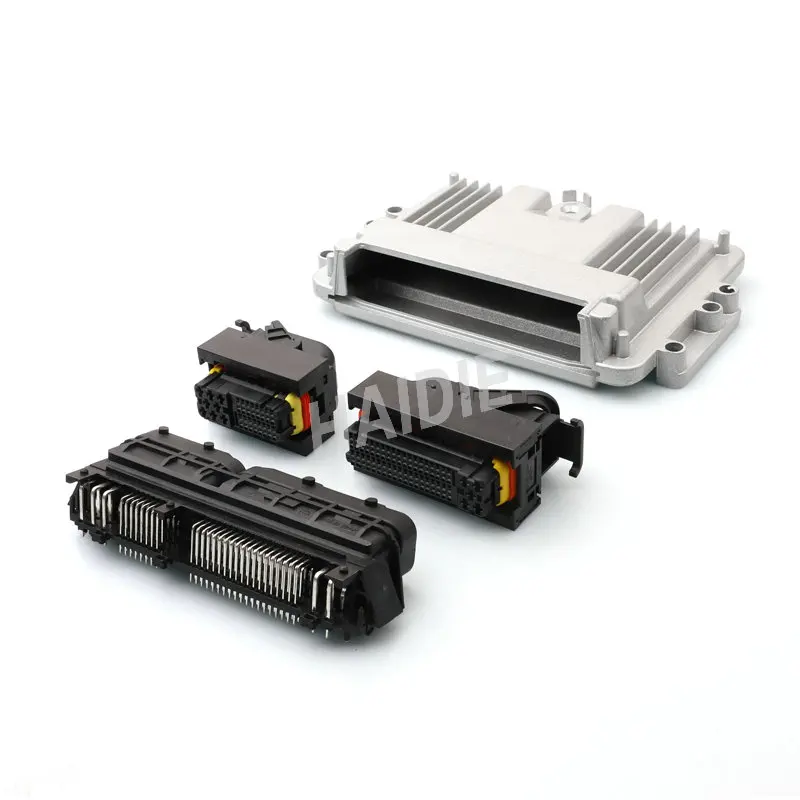
Ken, some good information on the [potential] connector used on these FICM's. I haven't found a 100% exact match but it looks like they might work with minimal modifications. There looks to be two little tabs in there that might need to be removed to connect with our harness side. The female (or berthing person 😝) side or the connector on the harness side will probably work without any change or modifications

Going to dump a bunch of links here so I can go back to look them up again later. Feel free to check them out


Attachments

  • ENG_CD_1241434_C15.pdf
    809 KB · Views: 1
  • ENG_CD_1241434_C14_pdf_1241434_c_drw-2003831.pdf
    806.8 KB · Views: 0
  • product-1241434-1.datasheet.pdf
    353.8 KB · Views: 0
  • Like
Reactions: kidturbo

2004LB7

Well-known member
Dec 15, 2010
6,970
2,137
113
Norcal
Edit, I think the actual connector part number is 368255-2. It doesn't have those tabs inside it


Attachments

  • ENG_CD_368255_H4.pdf
    257.5 KB · Views: 1
  • 368255-2-connector.zip
    661.5 KB · Views: 0
Last edited:
  • Like
Reactions: kidturbo

2004LB7

Well-known member
Dec 15, 2010
6,970
2,137
113
Norcal
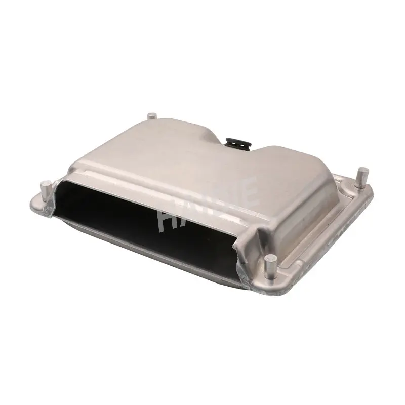
I wonder if our current FICM's will fit inside this enclosure. Would be good for those who relocate theirs


Another edit. Doesn't look like there is room for the caps. Looks cool though. This one would work despite how boring it looks. Comes with the correct connector from what I can tell

 
  • Like
Reactions: kidturbo

2004LB7

Well-known member
Dec 15, 2010
6,970
2,137
113
Norcal

2004LB7

Well-known member
Dec 15, 2010
6,970
2,137
113
Norcal
I wonder what the difference is between the 368255-1 and 368255-2 connector? Can't see any
 

2004LB7

Well-known member
Dec 15, 2010
6,970
2,137
113
Norcal
I only found one reference to the 368255-1 part number. Everything else is the -2 one.


Those rendering files will be a big help in designing a board that will accept the same connector. Getting the pin layout right could take multiple revisions. But with that file we can probably do it in one shot
 
  • Like
Reactions: 1FastBrick

07-6mt

New member
Sep 15, 2023
3
1
3
South
I stumbled across this while searching for FICM diagnostics - immediately joined. You guys have created an awesome thread. My LLY is down with FICM issues, so I am loving this approach and community involvement.

Count me in for this development. Highly interested in how this turns out. I would be down for being a tester with the development boards.

- Brad
 
  • Like
Reactions: kidturbo

1FastBrick

Well-known member
Dec 1, 2016
2,539
1,068
113
Junkyard
I stumbled across this while searching for FICM diagnostics - immediately joined. You guys have created an awesome thread. My LLY is down with FICM issues, so I am loving this approach and community involvement.

Count me in for this development. Highly interested in how this turns out. I would be down for being a tester with the development boards.

- Brad
Have you looked to see if your board is Physically damaged yet? It may be repairable. I believe 2004LB7 even fixed one that was damaged and it works.
 
  • Like
Reactions: 07-6mt

kidturbo

Piston Tester
Jul 21, 2010
2,537
1,366
113
Somewhere On The Ohio
www.marinemods.us
I only found one reference to the 368255-1 part number. Everything else is the -2 one.


Those rendering files will be a big help in designing a board that will accept the same connector. Getting the pin layout right could take multiple revisions. But with that file we can probably do it in one shot
I was going to purchase this one because it's the part # 368255-1, and you get 2 pieces. However the time to deliver, along with recent seller feedback rating made me reconsider. Any updates from the AB options?
 

kidturbo

Piston Tester
Jul 21, 2010
2,537
1,366
113
Somewhere On The Ohio
www.marinemods.us
One of those RUS guys answered your question already.. 368255-1 and 368255-2 are NOT the exact same socket. However you can hack the Germain version connector to work with Asian version socket. For you or I, probably not an issue. But for overall design, looks like a gotta get it right deal.

 
  • Like
Reactions: DAVe3283

2004LB7

Well-known member
Dec 15, 2010
6,970
2,137
113
Norcal
One of those RUS guys answered your question already.. 368255-1 and 368255-2 are NOT the exact same socket. However you can hack the Germain version connector to work with Asian version socket. For you or I, probably not an issue. But for overall design, looks like a gotta get it right deal.

The only thing I see in that link is he is comparing the 368255-2 to the 1241434-1 which we already figured out have the extra tabs or plastic inside. So far on what few photos there are of the 368255-1 connector, I don't see anything different than the 368255-2 one