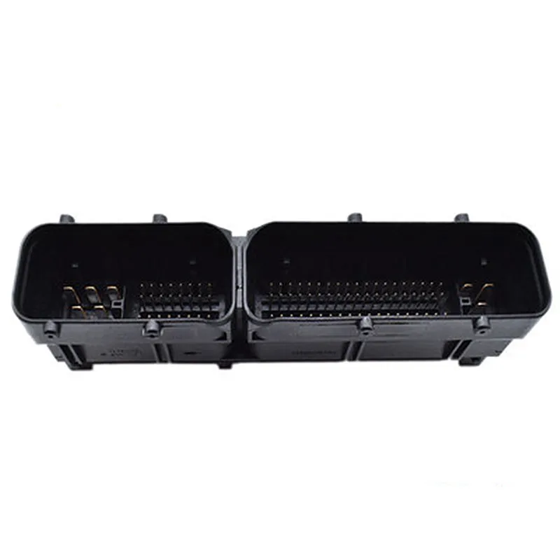
LLY Ficm

kidturbo

Piston Tester
Jul 21, 2010
2,565
1,418
113
Somewhere On The Ohio
www.marinemods.us
Yeah I see that now. Was looking at the -1 -2 part only.. LOL..

Here is what TE has to say about it. They don't even list a -1.

TE Part no Description
368255-2 BOSCH 121P HEADER ASSEMBLY
368255-3 BOSCH 121P HEADER ASSEMBLY
1-368255-2 BOSCH 121P HEADER ASSEMBLY
1-368255-3 BOSCH 121P HEADER ASSEMBLY
1-368255-5 BOSCH 121P HEADER ASSEMBLY
368290-1 ASS’Y CONNECTOR FOR JPT&MQS 81 POS
 

1FastBrick

Well-known member
Dec 1, 2016
2,693
1,186
113
Junkyard
I was going to purchase this one because it's the part # 368255-1, and you get 2 pieces. However the time to deliver, along with recent seller feedback rating made me reconsider. Any updates from the AB options?
What about this on AliExpress?

I did see this on AliBaba.
 

2004LB7

Super Moderator
Staff member
Dec 15, 2010
7,237
2,286
113
Norcal
I purchased one set from AliExpress and Alibaba.
What about this on AliExpress?

I did see this on AliBaba.
This is the one I got from AliExpress


You have to make sure to click on all the different connectors and add them to the cart. It totalled about $60 in the end. Slightly more than Alibaba and also doesn't come with a case
 

1FastBrick

Well-known member
Dec 1, 2016
2,693
1,186
113
Junkyard
I purchased one set from AliExpress and Alibaba.

This is the one I got from AliExpress


You have to make sure to click on all the different connectors and add them to the cart. It totalled about $60 in the end. Slightly more than Alibaba and also doesn't come with a case
Well, let's see what actually shows up...
Be good if we can atleast get the correct stuff and not have to modify anything.
Time will tell though...🤣
 

2004LB7

Super Moderator
Staff member
Dec 15, 2010
7,237
2,286
113
Norcal
Well, let's see what actually shows up...
Be good if we can atleast get the correct stuff and not have to modify anything.
Time will tell though...🤣
Yep. I'm hopping at least one shows up. I'm shooting for the new FUCM board to be able to plug right in with no modifications to the harness. Plus have some extras to make extension cables for easier testing
 

kidturbo

Piston Tester
Jul 21, 2010
2,565
1,418
113
Somewhere On The Ohio
www.marinemods.us
I'm caught up on the paperwork side of business, and heading down the the Bat Cave here shortly to hack up that LB7 harness.

Will see if can get the LB7 ECM and FICM on speaking terms today. Also posted a job on Upwork for someone to modify that Arduino emulator sketch so it outputs 8 evenly spaced time adjustable pulses in place of the cam signal, replicating our LLY or LB7 ECM. Having them write two versions of the code. One were the GPIO pins apply power at each pulse, and other cuts the power for pulse. Hopefully have that ready and tested within 24hrs, so pick up an Arduino Uno project kit from Walley World if your out and about.
 

kidturbo

Piston Tester
Jul 21, 2010
2,565
1,418
113
Somewhere On The Ohio
www.marinemods.us
Guess I did have another set of injector plugs in my secret wiring stash out in the weeds..
3dfedc88b21565b5395fcf02c7bf05ed.jpg


Sent from my SM-S901U using Tapatalk
 
  • Like
Reactions: wydopenLb7

2004LB7

Super Moderator
Staff member
Dec 15, 2010
7,237
2,286
113
Norcal
Measuring the ECM control signals for injector 1 & 2. From what I see these signals have everything needed to time the injectors and control PW. The crank signal is likely for redundancy and safety. You'll notice that the bottom signal (injector #2) moves closer to the top signal (injector #1) as the RPMs go up. And the PW changes too. You can clearly see the pilot and main injection signals

Source: https://youtu.be/hd15lVeviuI?si=xxTmAGnFYFY8LRrM


Source: https://youtu.be/KO6yoV_YYS0?si=FpnbhP78G4hiNQY_
 

kidturbo

Piston Tester
Jul 21, 2010
2,565
1,418
113
Somewhere On The Ohio
www.marinemods.us
Nice work. I was wondering how that's gonna look with the emulator driving it. With constant us pulse width values timed to crank teeth over wide rpm scale they will ultimately overlap at some rpm value.

Sent from my SM-S901U using Tapatalk
 

kidturbo

Piston Tester
Jul 21, 2010
2,565
1,418
113
Somewhere On The Ohio
www.marinemods.us
I couldn't bring myself to cut that perfectly good, and factory wired, relay box out of this kodiak harness. So I left it wired in and started chopping at the damaged section going to engine bail connectors.

Now just add battery, and a old school ignition switch, then trace out our crank/cam and fickem wires.

b0b3fe40de4d4233f0cc0da32ae6c9d3.jpg


Sent from my SM-S901U using Tapatalk
 
  • Like
Reactions: 1FastBrick

2004LB7

Super Moderator
Staff member
Dec 15, 2010
7,237
2,286
113
Norcal
Ken, how many wraps of wire around the injector line did it take to see the injector pulse on the scope? The best I was able to get was what looked like a sawtooth with no spacing and too low of voltage to seem reasonable. With the wire wrap I got nothing. Wrapped it around 16 times which I thought should have been more then sufficient.
 

kidturbo

Piston Tester
Jul 21, 2010
2,565
1,418
113
Somewhere On The Ohio
www.marinemods.us
Ya know what, I'll have to go dig thru those pics in my old PC. I may have ran it thru the center of an injector solenoid body itself. All that was several years ago. Recall it took a few attempts.

If you set your scope voltage to 2v or something, I'd think it should pick up the pulse clean. Basically, you're just creating an inductive pickup coil with the windings.

Either way, I'll tell ya tomorrow once I get these lmm connectors wired into our ficm harness. Then I'll have the full bench rig running for comparison.

42faf679006a5ff7a1acc9714e023a7b.jpg


Sent from my SM-S901U using Tapatalk
 

2004LB7

Super Moderator
Staff member
Dec 15, 2010
7,237
2,286
113
Norcal
I got nothing even as low as 500mV. Through the coil would make sense. But can't doo that with mine.
 

kidturbo

Piston Tester
Jul 21, 2010
2,565
1,418
113
Somewhere On The Ohio
www.marinemods.us
Took a break from the wiring, and after scrubbing the tape sticky from my fingers, started looking through those board diagrams and schematics I downloaded.

First thing, many of those PDF's are not text searchable, which means you have to look at each page to find the chips and associated pinout. Second, the IC's listed on board diagram, don't used IC numbers.. Just place holder numbers, IE R12, or S5800. However, I did find some useful info towards our goal. Starting with our main workhorse IC, and by verifying the boards layout by checking pics on google, got us one winner pretty quickly..

That Bosch 30402 series is a common IC used across many of the boards. And I found one of our FICM's little brother EDC15C2, used by Audi 1.8T Diesel. Plus the board layout in this particular section, matches up with our FICM pretty well. However it has a 30343. But besides that, it's same chip.

Bosch 30343 / 30402 / 30430 / 30595 / 30604 / 30606 / 30639
Relais driver sop36 for edc15c2 diesel ecu

So I have found the docs for this EDC15C2 board, then focused in on that particular IC. Which then gives me the layout schematics, that lines up pretty good with our board from there to the FETS. They flipped the chip 180, but overall, I bet the circuitry matched up. So below is the docs to hone in on it. Hope this helps..


EDC15C2 PCB

IMG_6942.JPG.resize.JPEG

In our board diagrams, that is shown here under file name ME75C3_ober.pdf

EDC15C2-Top.jpg


Our schematic below that matches this board, is ME75C3_d03049_1_obere_haelfte.pdf.

Likely many others share this same chip schematic, but this one looks to line up with our boards pinout. IE, chip S4000 has what looks to be serial TX RX pins going somewhere I've yet to nail down. But another IC, S1080 uses SPI. So guessing if we print out all the scematics for one design, and tape them together, one should be able to easily trace out the main parts on this EDC15C2 board, and verify against our LB7 FICM EDC15C8 board. Then take what we know, and apply to our EDC15C12 LLY FICM board.

Guessing same shared components structure goes with the power supply section, main processor, and so on.. Seems to me they just move those main sections around to fit whatever the specific build. But everything under all the EDC15's share same basic layout best I can tell. At worst, the docs give us pinout for each chip, which isn't found via normal Online searching..

EDC15C2-S4000.jpg

Hope that theory makes sense, it's late... :cool:
 

2004LB7

Super Moderator
Staff member
Dec 15, 2010
7,237
2,286
113
Norcal
was finally able to get some injector readings. I captured the injector control as well as injector command for #1.

some times it fired right near the middle of the control signal
31.png

but most of the time it fired at the end of the signal. didn't seem to change if I varied the RPMs
35.png

weirdly the pilot pulse looks larger than the main
 

2004LB7

Super Moderator
Staff member
Dec 15, 2010
7,237
2,286
113
Norcal
Tried them all. Was difficult to capture. I think the scope might be too slow to trigger properly. Since it's not a constant signal and has significant delay between the pulses it often just sees dead space. Then when the pulse happens it's slow to catch it. On some modes it jumps around too much to get a good screen shot. And for some reason this time it wasn't measuring the control signal voltage right. Always measured it at 5 volts. But something changed and it doesn't measure it right. I can always try again later and see if I can get it better