Here is our new 2016 output shaft sensor live, connected, and reporting good on the TCM. You can see the min / max voltage values. It shed 5 volts from it's disconnected state. Also note it actually never drops to 0v.


Next up is our Arduino Emulator running a 40 tooth pulse pattern. It outputs range between 0-5v, and the TCM accepts this pattern fine for both Input and Output lines.

Last up we have our early model sine wave sensor connected the 9v powered VR converter. I also tested with 12v power input, and no change in output noted. First thing ya notice is we are now in the mv scale when connected to the TCM. When disconnected, it outputs about the same 0-5v range as our Arduino...


What ya think ??
Next up is our Arduino Emulator running a 40 tooth pulse pattern. It outputs range between 0-5v, and the TCM accepts this pattern fine for both Input and Output lines.
Last up we have our early model sine wave sensor connected the 9v powered VR converter. I also tested with 12v power input, and no change in output noted. First thing ya notice is we are now in the mv scale when connected to the TCM. When disconnected, it outputs about the same 0-5v range as our Arduino...
What ya think ??


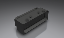
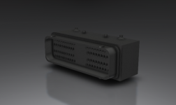
 CAD..
CAD..