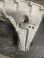
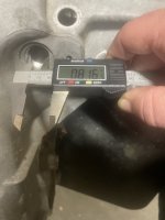
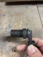
It is a M22x1.5 just a hair smaller than 7/8-18. That is where I have ran into a few issues with making an adapter. Luckily I have a rear transfer case half that was cracked laying in my scrap pile to play with. Problem is #1 the new sensor small end is the same size as the inside diameter of the threads - no room for an adapter. #2 the new sensor is slightly shorter in length from base surface to tip. So no matter we simply can’t make an adapter like I had hoped as it’s already to short and wouldn’t get close enough to the 40 tooth wheel to pick it up. The 15.5-16 transfer case is machined down lower where the sensor sits in. There is plenty of material there to mill the old one down but that would require a lot of machining and such and at that point you could simply buy the new rear case half for $200 and swap the back case half as all the internal parts are the same other than the input shaft from the trans because 11-up has a larger spline shaft on the trans to mate to the transfer case and the front of the case is different because they changed the mounting pattern to fix the issue with cracking cases. But that doesn’t mean we can’t make a thread in adapter and use a different smaller diameter threaded in Hall effect sensor. There are a lot of options out there I’ve been looking at over the past 24hours. I can throw a piece of rod in the lathe and make a stainless steel or even aluminum adapter that threads in, question is do I put the new sensor into the lathe as well and see if I can turn it down to simply fit into the adapter with sealant and retaining compound, which would allowed the lower depth, or go with a different DC Hall effect sensor entirely that’s smaller diameter threaded that would just thread through the adapter.
T87 Swaps
Discovered a slightly BIG freaking issue with sticking this T87 into the 2005-2010 truck chassis. While we can make the TCM speak happily with the E35A/B ECM by tagging on a few missing packets of required data, that can be assembled from existing CANbus data, the TCM really doesn't like any...www.duramaxdiesels.com
Not sure on the thread, will see if I can locate my pitch tool.
Sent from my SM-S901U using Tapatalk
T87 Swaps
- Thread starter kidturbo
- Start date
You are using an out of date browser. It may not display this or other websites correctly.
You should upgrade or use an alternative browser.
You should upgrade or use an alternative browser.
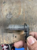
Well that takes the Easy out of the equation again.. I was betting on that new sensor being a smaller diameter. Back to the drawing board..
Sent from my SM-S901U using Tapatalk
Sent from my SM-S901U using Tapatalk
I'm located in southeast Ohio, so I'm pretty close to ya. @pl_silverado said he was gonna send me a new style sensor, but I can grab one at the local parts store also if need.
IMO, the easy fix is just stick one of these little dual line VR to Hall converters in the harness and leave all the factory speed sensors alone. Then, if any reason ya wish to swap back to an A40/50, it's simply unplug the T87 adapter cable, connect the old style TCM, and done.
Sent from my SM-S901U using Tapatalk
I’ll send it all this week. Been gelled up in Colorado waiting for a break in the weather to head back east. Hopefully hitting the road tomorrow.

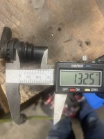
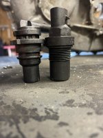
The end of it is a smaller diameter. I didn’t have the other style thread in vss handy for measurements and didn’t feel like running to the shop last night. Going to run to Hicksville auto recyclers today and see if they have a junk 2016 tcase laying around that I can burrow for case measurementsWell that takes the Easy out of the equation again.. I was betting on that new sensor being a smaller diameter. Back to the drawing board..
Sent from my SM-S901U using Tapatalk
@kidturbo just curious but have you tried a 15.5-16 t87 and LML calibration instead of a t87a and l5p calibration? I’ve been curious because of a few module changes in the LML trucks. In 14 they went to the new bcm that they used up through 19 I believe but all other modules besides the abs stayed the same and in 14-early 15 they still had the A50 module and e86a ecm. In 15.5 they changed to the e86b and t87 but were still using the same abs module as the 14 that had the e86a ecm. Doesn’t necessarily mean anything for the lmm with e35b ecm but seems there must be alot of canbus message carryover to the t87 15.5-16 truck calibrations from the a50 trucks or they rewrote a lot of code in the bcm, ecm, and ebcm to work with the t87. Really shouldn’t be to many bcm messages going to the tcm except for brake petal activation, tap shift up and down, and maybe tow/haul “I assume goes bcm to tcm but the ecm also has logic for tow haul so not sure on that”. I spent about 2 hours talking to the guys at Hicksville auto recyclers and came home with the elusive t87 bracket that goes in place of the a50 on the fan shroud. Also took a little time to play with vss sensor some more. I had the threaded sensor length wrong and in fact I’m back on board with an adapter as the new sensor from seal base to tip is actually longer by about .080”. So going to play with that more tonight and see if I can machine the new sensor down enough to slide down through the old threaded body if I gut it. If it works then I can spin out some stainless adapters and simply machine down the new sensor to fit.The end of it is a smaller diameter. I didn’t have the other style thread in vss handy for measurements and didn’t feel like running to the shop last night. Going to run to Hicksville auto recyclers today and see if they have a junk 2016 tcase laying around that I can burrow for case measurements
Attachments
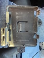
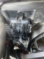
Nice find on the bracket.. Please share a picture mounted up if ya have one.
So far what we've been testing with is only the 15-16 T87 hardware and OS versions for diesel an gassers. However the hard data for reference, is only for the T87A. Nobody here has actually tested an 87A yet, and we only have logged actual truck data from an 18 L5P. Plus what all the LML stuff @Cougar281 has wired up on his bench . Then we verify what messages are listed as Required in the 87A data list, and verify those in the T87 running. That's where the differences to LML- LMM years has popped up. I'm guessing the 14.5-15 BCM OS would probably satisfy the TCM data requirements. Leaving only the EBCM to deal with. And it's possible we can fiddle with the T87 bin files enough to satisfy some differences there.
Leaving just a few ECM torqure related messages to sort out. So I can likely have an early LML truck running happy with a T87 tomorrow, if had one handy to try with. But the goal is cover the whole line back to LBZ, which a bit more involved than whats been proven by others so far.
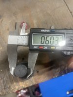
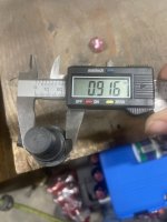
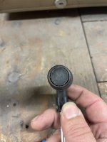
Alright. I’m guessing the 09-10 trucks with 4 wheel abs and stabilitrac may be less of a problem than the ones with out and 06-08. I need to drive my 10 down so you can get some data from it. On another note I was able to trim down the vss sensor like I had hoped without damaging it. Actually over trimmed it but I didn’t use my lathe I just used the belt for now for first testing and used the old vss for a template and here you go. Thinking a small set screw from the side to keep it solid. Thread the adapter in, put a bead of sealer around the flange of the sensor and slide it in, tighten the set screw and done. Ideas?Nice find on the bracket.. Please share a picture mounted up if ya have one.
So far what we've been testing with is only the 15-16 T87 hardware and OS versions for diesel an gassers. However the hard data for reference, is only for the T87A. Nobody here has actually tested an 87A yet, and we only have logged actual truck data from an 18 L5P. Plus what all the LML stuff @Cougar281 has wired up on his bench . Then we verify what messages are listed as Required in the 87A data list, and verify those in the T87 running. That's where the differences to LML- LMM years has popped up. I'm guessing the 14.5-15 BCM OS would probably satisfy the TCM data requirements. Leaving only the EBCM to deal with. And it's possible we can fiddle with the T87 bin files enough to satisfy some differences there.
Leaving just a few ECM torqure related messages to sort out. So I can likely have an early LML truck running happy with a T87 tomorrow, if had one handy to try with. But the goal is cover the whole line back to LBZ, which a bit more involved than whats been proven by others so far.
Attachments
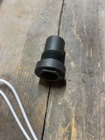
My only concern would be the set screw in plastic becoming 'unset' and allowing it to move... Could be a problem if that happened. Might that sensor Ken mentioned and I found an 'uber cheap' version of on Amazon be a possible option?
My only concern would be the set screw in plastic becoming 'unset' and allowing it to move... Could be a problem if that happened. Might that sensor Ken mentioned and I found an 'uber cheap' version of on Amazon be a possible option?
Not really. That sensor is the wrong thread and as far as I could find it’s a vr sensor and not a Hall effect sensor. No different than what we currently have in there. It’s just the older 3/4” thread version for the 88-2000ish vehicles. I see your concern though. My other thought was when I machine the sensor down I could put a small grove in it and then put a series of cross holes in the adapter that we could push a roll pin into that would engage across that grove, saying series of holes because much like a set screw same way it would depend on where the adapter tightened down as clocked as I’m sure no two cases will be threaded exactly the same and only would have access to the set screw from the back because of the pocket around it. In all reality if we used something like the gray gm crankcase sealant around the top 1/2-3/4” of the sensor when you pushed into the adapter then the set screw or pin would only be there to hold in place until the sealant cured. If you’ve ever had to pull an engine cover with that on it you already know the sensor would never come out without some major prying motivation once cured. In a bulk application I still plan to make the adapters out of stainless not plastic and with that you could put a dab of blue locktite on the set screw without concern of it backing out.My only concern would be the set screw in plastic becoming 'unset' and allowing it to move... Could be a problem if that happened. Might that sensor Ken mentioned and I found an 'uber cheap' version of on Amazon be a possible option?
Yeah I'm with ya on busting the old sensor out of that metal unit, and then epoxy the new sensor into it. Need a way to set that depth, and the thread with an O-Ring for spacers if needed be easy to test with.My only concern would be the set screw in plastic becoming 'unset' and allowing it to move... Could be a problem if that happened. Might that sensor Ken mentioned and I found an 'uber cheap' version of on Amazon be a possible option?
Just saw your post about the different threads. So plastic should do it then.
Oh, well that's different. The adaptor made out of some sort of metal, stainless or otherwise, with blue locktite, that's not going anywhere, other than maybe the sensor moving on the set screw, but that part is unlikely if the set screw is solid.Not really. That sensor is the wrong thread and as far as I could find it’s a vr sensor and not a Hall effect sensor. No different than what we currently have in there. It’s just the older 3/4” thread version for the 88-2000ish vehicles. I see your concern though. My other thought was when I machine the sensor down I could put a small grove in it and then put a series of cross holes in the adapter that we could push a roll pin into that would engage across that grove, saying series of holes because much like a set screw same way it would depend on where the adapter tightened down as clocked as I’m sure no two cases will be threaded exactly the same and only would have access to the set screw from the back because of the pocket around it. In all reality if we used something like the gray gm crankcase sealant around the top 1/2-3/4” of the sensor when you pushed into the adapter then the set screw or pin would only be there to hold in place until the sealant cured. If you’ve ever had to pull an engine cover with that on it you already know the sensor would never come out without some major prying motivation once cured. In a bulk application I still plan to make the adapters out of stainless not plastic and with that you could put a dab of blue locktite on the set screw without concern of it backing out.
The way I did this one it bottoms out to the same depth as the original sensor parts. That goes all the way down and bottoms out on an oring when you thread it in. While at Hicksville Auto we went to their rebuild area where they do the transfer cases and checked the sensor distance between a 2007-10 case 11-15 case and a 16 case from the output shaft wheel to the sensor and they all use the same spacing within about .003-.008” of each other which could be due to variances in the case itself. So my hope is that by settting the new sensor into the adapter at the same depth as the original vss it should work accordingly.Yeah I'm with ya on busting the old sensor out of that metal unit, and then epoxy the new sensor into it. Need a way to set that depth, and the thread with an O-Ring for spacers if needed be easy to test with.
Just saw your post about the different threads. So plastic should do it then.
Took a second to set the t87 into the bracket and onto the lmm fan shroud. I did notice the wire exit is going toward the fan lm the lmm where on the lml fan shroud it’s going down because the tcm is turned 90 degrees but shouldn’t be an issue and I have to do some looking but I’m pretty certain molex makes both the left and right exit plugThe way I did this one it bottoms out to the same depth as the original sensor parts. That goes all the way down and bottoms out on an oring when you thread it in. While at Hicksville Auto we went to their rebuild area where they do the transfer cases and checked the sensor distance between a 2007-10 case 11-15 case and a 16 case from the output shaft wheel to the sensor and they all use the same spacing within about .003-.008” of each other which could be due to variances in the case itself. So my hope is that by settting the new sensor into the adapter at the same depth as the original vss it should work accordingly.
Attachments
So I found it. The t87 plug number for the LML would be
34822-0013
And for the lmm 2010 and older trucks since the module goes up and down vs side to side we would want to use plug number34822-0023
This swings the latch the opposite direction and exits the wire the other way as well but the same top cap fits both34565-0003
Thanks for hashing that out. I knew it would be a tight fit up there, but at least we have off the shelf connector options.So I found it. The t87 plug number for the LML would be
34822-0013
And for the lmm 2010 and older trucks since the module goes up and down vs side to side we would want to use plug number
34822-0023
This swings the latch the opposite direction and exits the wire the other way as well but the same top cap fits both
34565-0003
The connector I got with the T87A out of the 2017 Camaro goes the correct direction (opposite of the one in your pic) for the location, so boneyard finds are also an option.
I actually have all the part numbers for the plugs both left and right hand, plug covers, the pins, cavity plugs, and pin seals for the power and ground terminals. I have them all coming to have in stock. No sense in searching bone yards that will let you cut out plugs when it really doesn’t cost that much to make nice new ones. The plug itself is the expensive part at about $18. Pins are cheap pennies.The connector I got with the T87A out of the 2017 Camaro goes the correct direction (opposite of the one in your pic) for the location, so boneyard finds are also an option.
What ya find for terminal cross reference numbers? I'm just placing an order for a few connectors.I actually have all the part numbers for the plugs both left and right hand, plug covers, the pins, cavity plugs, and pin seals for the power and ground terminals. I have them all coming to have in stock. No sense in searching bone yards that will let you cut out plugs when it really doesn’t cost that much to make nice new ones. The plug itself is the expensive part at about $18. Pins are cheap pennies.
The two corner pins for power and ground are Yazaki #7116-4152-02 and the seals are #7158-3113-40. The rest of the pins Molex #34736-0028 which only seem to come in a reel or cut strip through Mouser but I haven’t checked with anywhere else yet and those cavities have a built in seal. The cavity plugs for all the non wired cavities is Molex #34586-0001What ya find for terminal cross reference numbers? I'm just placing an order for a few connectors.