Crank Plots

Fingers

Village Idiot
Vendor/Sponsor
Apr 1, 2008
1,713
84
48
White Oak, PA
Small Steps

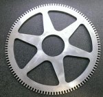
Finally got around to making a tone wheel for the front of the crank. It has the same tooth count as the starter gear. It will attach, via a hub, to the middle of the harmonic balancer.

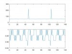
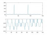
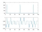
Using a prox sensor, like the one on the crank reluctor, I should be able to compare the front and back crank signals with a scope. Any phase shifting will show up as the signals getting out of phase.

I had done something similar using just the build in crank sensor, but the tooth count difference meant I had to use software to pull anything useful out of the data.

attachment.php
 

Attachments

  • IMAG0029 (2).jpg
    IMAG0029 (2).jpg
    87.5 KB · Views: 195

joesixpack

New member
Jan 17, 2011
5
0
0
I'd expect to see some deceleration/acceleration on each firing stroke if your resolution was great enough. That signal makes no sense.
 

Fingers

Village Idiot
Vendor/Sponsor
Apr 1, 2008
1,713
84
48
White Oak, PA
Actually, The Accel/Decel is there, but they are much harder to see at higher RPM. Data points on those plots are at 6° which is good for velocity measurements. 60-150 counts per data point depending on sampling rate.

Changing the data to velocity and scaling the plot as a percentage of max velocity gives these which show your expected variation. The top plot is the raw counts per tooth data and the bottom the velocity as a percentage of Max

Even so, there seems to be another frequency at work over the 4/rev. More so in some of the plots. This is even when accounting for the published dither in the DAQ's sampling rate.

These are all from old data that was not intended to look for velocity or torsional changes. They also only look at 2 revolutions of the crank which does not give me enough data to do a proper Fourier transform and find other harmonics.

I suspect the crank is resonating torsionally. Thus the new tone wheel for the front. The tooth count could have been a lot less, but I decided to start with the same count as the flywheel.

To see the flex when running up to about 4000 RPM, I will need to sample at
240KHz to get 1/10° increments. However, I expect to see much more flex at the lower RPMs. I think that is where the problem is.
 

Attachments

  • plot1.jpg
    plot1.jpg
    30.6 KB · Views: 67
  • plot2.jpg
    plot2.jpg
    29.7 KB · Views: 58
  • plot3.jpg
    plot3.jpg
    30 KB · Views: 57

RPM Motorsports

smokinum
May 13, 2008
3,271
10
38
Central Valley Ca.
Got another broke crank in the shop if you want me to send it your way. Behind #1 main, I can cut the other side off for less shipping weight if you want to inspect it. GM replacement motor 20k mi.

PS: need to get a set of std or .020 Pistons headed this way asap, I'll Ring you tomorrow.
 

fastpunker

adrenaline junkie
Feb 7, 2012
215
1
16
Lake Havasu City, AZ
subd.
Nice write up and great to see someone digging this far into it Fingers!


Got another broke crank in the shop if you want me to send it your way. Behind #1 main, I can cut the other side off for less shipping weight if you want to inspect it. GM replacement motor 20k mi.

PS: need to get a set of std or .020 Pistons headed this way asap, I'll Ring you tomorrow.


Can you post some Pictures of the broken crank... preferably close ups of the broken edges? I am curious to see what the fracture properties look like... crack propagation, deformation, etc. I am in no way trying to step on anyone's toes by asking, just curious for myself given my current job and schooling.
 

Fingers

Village Idiot
Vendor/Sponsor
Apr 1, 2008
1,713
84
48
White Oak, PA
I don't need another one laying around the shop. Thanks for the offer.

There are a number of pictures on this site of broken cranks. Most of them are excellent.