Crank Plots

Fingers

Village Idiot
Vendor/Sponsor
Apr 1, 2008
1,713
84
48
White Oak, PA
I've been working on this for a while using the raw data. I finally decided I needed to start making plots to show what I am talking about.

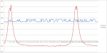
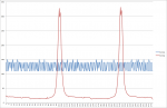
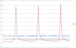
The Blue line in these plots represents the time between crank pulses. The variation is visible at all RPMs, but fades in my plots because the duration of my sample rate approaches the frequency of the variation. The data is grainy, but outside the error function for the sensors and all. So it is not noise.

What these plots show is something happening to vary the crank speed drastically on a consistent basis. I don't always catch every instance of the event in a sample frame, but the variation is always there on all my plots and is always ~12°-18° (2-3 reluctor teeth). The speed variation is about 10% and is happening very very quickly.

My Question is: What is happening ~20-30 times a revolution? 10% is a huge variation.
 

Attachments

  • dunbar1.png
    dunbar1.png
    43.5 KB · Views: 150
  • tom1.png
    tom1.png
    60 KB · Views: 130
  • Dunbar2.png
    Dunbar2.png
    47 KB · Views: 274

Fingers

Village Idiot
Vendor/Sponsor
Apr 1, 2008
1,713
84
48
White Oak, PA
I wouldn't call it "normal".

The force required to fluctuate the crank speed that quickly is huge.
 
Last edited:

Fingers

Village Idiot
Vendor/Sponsor
Apr 1, 2008
1,713
84
48
White Oak, PA
PTO? You mean front of the engine? Stock and dual fuelers. Doesn't seem to matter as far as this variation is concerned.
 

coker6303

Keep Calm and Chive On!!
Aug 6, 2009
2,484
0
36
39
Houston, TX
PTO? You mean front of the engine? Stock and dual fuelers. Doesn't seem to matter as far as this variation is concerned.

Sorry, I meant the output side to the converter. Was this on a truck under a cruise load, neutral, etc. Just curious on what resistance it was seeing down stream of the drivetrain.
 

Fingers

Village Idiot
Vendor/Sponsor
Apr 1, 2008
1,713
84
48
White Oak, PA
The plots I posted are just representative of what I have in my library. They cover most driving conditions, including sitting in neutral. Vibration seems to be there for all of them. That is, it is not coming from the converter end unless it is the tranny pump.

On another note. I see the oil pump has 10 vanes and runs at twice the crank speed for 20 hits per rev.
 

56taskforce

Well-known member
Mar 30, 2014
1,074
51
48
It would be interesting to see the same plot on one with an altered firing order cam. Maybe this is what is breaking cranks?
 

duratothemax

<--- slippery roads
Aug 28, 2006
7,139
10
0
Wyoming
So I wonder if the LML ECM that does real-time injector/cylinder power balancing at all RPM's instead of just idle is doing anything to help? Or does it not make a difference since its a "reactive" adjustment?

I would be curious to see what a stock LML shows as far as those measurements.
 

Fingers

Village Idiot
Vendor/Sponsor
Apr 1, 2008
1,713
84
48
White Oak, PA
For this variation, probably no difference. Not power related or adjustable. However, there are lower frequency variations too that I will get into later.
 

Fingers

Village Idiot
Vendor/Sponsor
Apr 1, 2008
1,713
84
48
White Oak, PA
I've been playing with this off and on for a bit since my last post. The problem was trying to glean a pattern out of all the mess.

So on a whim, I changed my basis for the plots from crank degrees, to time. This allowed me start to see a frequency relation between the crank speed variations. If I run through the data frames as the engine revs up, you can see the variation amplify and recede and amplify. The waves seem to be certain frequencies. In my engine's case, about 188HZ, but I have data for others that indicate other frequencies for those engines.

I am still not sure where the driving input is coming from, but it is clear to me that when it lines up with the natural harmonic of the crank, it amplifies.

I also notice a fair bit of variation from engine to engine. In my case, the natural frequency changed from one build to the next.

All this is from my library of chamber pressure plots that I have collected. They just so happen to have the crank signal in them too but I was not focusing on that at the time.

I hope to cobble together something here in the next week or two to specifically look at the crank signal in higher resolution.
 

SilveradoTwins02

Hopefully twins soon
Aug 5, 2014
194
0
0
Hanover PA
I have heard that there are not any dun. Questions and maybe this has been asked in other threads in the past. So here it goes
It seems the this issue has been around since the beginning of the DMax
It looks as the aftermarket has come up with this AF cam just like a lot of gasser race engines run. So why hasn't GM engineers switched over to this AF cam in the newer generation D Max engines zig is ask needed to keep the cranks safe from failure ??
 

Fingers

Village Idiot
Vendor/Sponsor
Apr 1, 2008
1,713
84
48
White Oak, PA
First, GM would have to admit there was a problem. They have not.

Second, they would want to have a solution. They do not.

Lastly, I think the Alt-fire helps, but until I can develop a way to compare stock to Alt-fire, we will not know if it is truly the answer. My pet theory right now is that the harmonics vary significantly from engine to engine and that a one dampner fits all approach does not work.

I think we got the firing order we did because the Dmax project people wanted and needed the engine to be different in as many ways as possible from the competition and previous GM diesel V8s (6.5, 6.2...)
 

hntngkd

Member
Jun 24, 2013
162
5
18
Attica, Mi
I have heard that there are not any dun. Questions and maybe this has been asked in other threads in the past. So here it goes
It seems the this issue has been around since the beginning of the DMax
It looks as the aftermarket has come up with this AF cam just like a lot of gasser race engines run. So why hasn't GM engineers switched over to this AF cam in the newer generation D Max engines zig is ask needed to keep the cranks safe from failure ??

GM engineers have never seen a crankshaft failure at the Pontiac Powertrain testing facility that i know of. I have asked dyno operators that have been here for years and they say the same thing. Crankshaft failure is not a known problem to them.
 

LBZ

Super Moderator
Staff member
Jul 2, 2007
9,903
149
63
45
B.C.
GM engineers have never seen a crankshaft failure at the Pontiac Powertrain testing facility that i know of. I have asked dyno operators that have been here for years and they say the same thing. Crankshaft failure is not a known problem to them.

I've got a broken one from a stock engine I can send them to look at if they like!:D

Fingers, you need someone with one of the new front covers that can have the cam quickly swapped out (relatively speaking) and do some back to back testing stock profile cam to stock AF. You should be able to overlay the plots and compare no? If I was closer I would help you out with this.
 

Fingers

Village Idiot
Vendor/Sponsor
Apr 1, 2008
1,713
84
48
White Oak, PA
I've lined up a builder with an engine dyno. He says he will put multiple mule engines he has on the dyno for me to compare and even swap out some parts if warranted.

Lord knows how much that is going to cost me, or how long it will take to gather the info.....