Porting to reach high rpm breathing

Fahlin Racing

New member
Aug 22, 2012
330
0
0
NE Ohio
Sorry, I won't be spending the money when I have to build a circle track Ford Ranger, build a flow bench and planning my FED. Porting is doing fine for now. I just need to buy some long arbors for down by the bowl. As far as the adding material, I meant more within the port in some areas if needed.

I suppose I will have to inject a dye while the head is flowed to find inactive areas.

Do they have a sheet of flow numbers for the Wagler/Brodix heads on their website?
 

Fahlin Racing

New member
Aug 22, 2012
330
0
0
NE Ohio
I'll pass on that, I will wait for them to go public from the company. Thank you though.

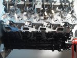
Duramax3_zps7d9b5fe7.jpg


Duramax_zps068011c4.jpg
 

Fahlin Racing

New member
Aug 22, 2012
330
0
0
NE Ohio
Paging Mark @ Danville, would you happen to have any pictures of the intake and exhaust rocker arms? Maybe Ben or someone?

After looking at the valves since I have cleaned them up. The exhaust is a more steep tulip valve, where the intake valve is less steep going to the stem but not quite a nailhead valve, I think you can run different valve designs in each app and have more than one flow efficiency possibility. I will try to get a good picture of them.
 

x MadMAX DIESEL

<<<< No Horsepower
Dec 30, 2008
7,535
1
38
34
Lexington, Ky
This is an awesome convo guys (no homo) so far we've got 270 put of stock heads that don't last long atall, but perform. What's next out of these stockers, or brodix heads? Very interesting !!! I love it
 

MarkBroviak

DMax Junkie
Vendor/Sponsor
May 25, 2008
2,141
499
83
Danville Indiana
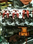
This is all I have on my phone, if you need better I can get some at work Friday or Monday.
 

Attachments

  • marks phone 024.JPG
    marks phone 024.JPG
    135.8 KB · Views: 109
  • marks phone 099.jpg
    marks phone 099.jpg
    197.6 KB · Views: 110

Fahlin Racing

New member
Aug 22, 2012
330
0
0
NE Ohio
Thank you again Mark, I appreciate it! So the Duramax already has a very sturdy rocker system that has be proven on other engine designs as well. I believe there may not be, or if so, very little problems here? Any side view of them in general Mark?

I wonder what the scrub pattern looks like on the valve bridge top and if it shows any particular pattern in the valve stem sections.

Magnus, I believe you will appreciate this one. Jim Mcfarland mentions this in one of his turbulence articles in a magazine I am subscribed to which I finally caught up on reading. Still haven't read the newest issue of Diesel Power though, probably this weekend.

Source: Circle Track - March 2013 Enginology column
"...some fluid dynamics textbooks suggest that the thickness of the boundary layer may be defined arbitrarily as the distance from the passage walls where the difference between zero velocity (at the surface) and at 1 percent of the flow rate of the outer flow...."
 

Magnus

New member
Jun 22, 2013
144
0
0
That's interesting, I've never heard it arbitrarily defined as anything... Usually it was specified as in "the edge of the thermal boundary layer will be determined by the point where the differential flow velocity reaches 75% of peak velocity for the given cross sectional area"

Then you'd have to go through the system and determine at different points where the thermal boundary layer was thickest and have to offer a better profile for that area or some such nonsense.

Yay college

But yes effectively the thermal boundary layer is the area of reduced flow due to adhesion between the fluid and the walls of the container. Basically the flow velocity is 0 against the wall and gradually increases more or less according to a second order differential equation until it reaches a peak flow near the center area. You can define the boundary layer based on the point away from the wall where a molecule would reach a certain percentage of the peak flow rate or based on calculating the area of slowed flow at the edges where say only 10% of total mass flow occurs.
 

jkholder09

New member
Jan 8, 2012
1,188
0
0
Maryland
That's interesting, I've never heard it arbitrarily defined as anything... Usually it was specified as in "the edge of the thermal boundary layer will be determined by the point where the differential flow velocity reaches 75% of peak velocity for the given cross sectional area"

Then you'd have to go through the system and determine at different points where the thermal boundary layer was thickest and have to offer a better profile for that area or some such nonsense.

Yay college

But yes effectively the thermal boundary layer is the area of reduced flow due to adhesion between the fluid and the walls of the container. Basically the flow velocity is 0 against the wall and gradually increases more or less according to a second order differential equation until it reaches a peak flow near the center area. You can define the boundary layer based on the point away from the wall where a molecule would reach a certain percentage of the peak flow rate or based on calculating the area of slowed flow at the edges where say only 10% of total mass flow occurs.


I believe this principle is applied when the walls are left rough to create turbulance. the turbulance acts as a bearing to speed the center flow which is 90% of the mass anyway. This was always my argument for leaving the porting of a runner or head rough vs smoothing to a lower ra finish.
 

Magnus

New member
Jun 22, 2013
144
0
0
But then all the other numbers on port flow mentioned earlier in the thread indicate that you could buy heads from Brodax or Brodix or Brodie Jenner or whoever you want... The flow capabilities are drastically higher than the limits posed by structural integrity of the engine, let alone what any turbo system used by people on this forum to date can flow. We're optimizing the strong point and I'm still confused as to why.

If you want to make an everyman's port job, model and execute a consistent cross sectional area with as consistent a cross sectional perimeter length as possible with unshrouded optimally sized valves and see what you can gain.

Or just up your boost and swap in a cam. Heck, make it an alternate firing order cam and solve an actual weak point at the same time.:thumb:
 

Magnus

New member
Jun 22, 2013
144
0
0
I believe this principle is applied when the walls are left rough to create turbulance. the turbulance acts as a bearing to speed the center flow which is 90% of the mass anyway. This was always my argument for leaving the porting of a runner or head rough vs smoothing to a lower ra finish.

Negative the stationary port walls do not follow the same aerodynamic principles as a spinning golf ball, and if they did the optimal disruptive pattern would not be the relatively random roughness of a factory aluminum cast.

Golf ball turbulence serves to INCREASE boundary layer influence in order to extend the point of boundary layer separation further on the backside of the ball and reduce the vacuum generated behind the ball as well as any vortex shedding as the ball travels. This reduces losses due to pressure differentials as could be understood through Bernoulli's principle.

You should most definitely polish a surface to reduce adhesion and thus reduce boundary layer behavior. Increased boundary layer behavior in an enclosed flow path nearly always reduces total flow.
 

LtEng5

Member
Mar 24, 2013
74
0
6
CT
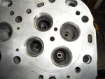
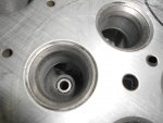
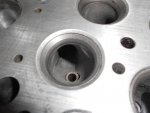
in wanting to see some clearer images of the area in the port at the valve throat that material could be removed from..... notice that the 2 intake runners are just under HALF of opening diameter of the valve and the exhaust side is just as bad.
 

Attachments

  • DSCN1384.jpg
    DSCN1384.jpg
    160.3 KB · Views: 72
  • DSCN1589.jpg
    DSCN1589.jpg
    150.5 KB · Views: 69
  • DSCN1582.jpg
    DSCN1582.jpg
    134.4 KB · Views: 70

LtEng5

Member
Mar 24, 2013
74
0
6
CT
You should most definitely polish a surface to reduce adhesion and thus reduce boundary layer behavior.


So... if the ports were to be polished like this....... that should be good to reduce the boundary layer..... yes...??
 

Attachments

  • DSCN1718.jpg
    DSCN1718.jpg
    169.4 KB · Views: 102

Magnus

New member
Jun 22, 2013
144
0
0
So... if the ports were to be polished like this....... that should be good to reduce the boundary layer..... yes...??

Word. The less friction the surface generates as fluid flows through it the more fluid you get.

And you're right the shrouded valve area is where to pick up the most
 

Fahlin Racing

New member
Aug 22, 2012
330
0
0
NE Ohio
You should most definitely polish a surface to reduce adhesion and thus reduce boundary layer behavior. Increased boundary layer behavior in an enclosed flow path nearly always reduces total flow.

We must remember there are DIFFERENT levels of polishing as well.

I was told flow improvement changes less than 1 percent when compared with full polish and 36 grit finish. What we must achieve is a boundary layer not so thin as to separate from the surface but not so thick to do as well and create a flow choking situation due to turbulence. The happy medium.

Nice work Lt. Good pictures.
 

Fahlin Racing

New member
Aug 22, 2012
330
0
0
NE Ohio
Lt, I see you removed the ridge on the roof and left the floor ridge that resides between each valve flow-path. What are your thoughts there?

One thing would be pretty interesting is how these two flow paths join to drive the turbocharger.
 

LtEng5

Member
Mar 24, 2013
74
0
6
CT
We wanted to leave the raised floor of the outer valve to help with gas exiting the cylinder. making th floor 100% flat up to the valve throat will hurt flow numbers as the raised floor acts like a ramp; hopefully helping to accelerate the gas out of the cylinder. making the floor flat would also require a large amount of material to be removed to re-curve the throat.....
 

Fahlin Racing

New member
Aug 22, 2012
330
0
0
NE Ohio
An ever morphing shape as I am trying to imagine the exhaust port is rolling through the brain with your thought there. Very exciting stuff! A while back I took my inside caliper and measured the intake port and exhaust port in stock form.

Intake: 1.08" x 1.31 = 1.4148 + or - square inches at manifold mating surface
Exhaust: 1.36" x 1.29" = 1.7544 + or - square inches at manifold mating surface

Valve area per valve, add together to get our total valve area of usable flow area that we try to utilize and form our flow curve lift-off to set-down in either tract for those reading/thinking.

Valve area on one exhaust valve
Stem dia. 7mm or .275591"
Valve dia. 31mm or 1.2195" on the valve I am measuring

(1.2195 squared x .7854) - (.2755" squared x .7854)
1.1680 - 0.0596 = 1.1084" area

Valve area on one intake valve
Stem dia. same as above
Head dia. 33mm or 1.2936" on the valve I am measuring

(1.6734" x .7854) - (.2755" squared x .7854)

1.3142 - 0.0596 = 1.2546" area

As we port towards the valve, and checking with a telescoping gauge. I have a feeling I may need to buy a longer one if its possible to make sure I have made some gentle progress in terms of CSA changes with the cartridge roll. Hmm.

Back to thinkin'...:thumb: