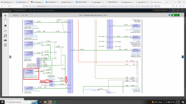
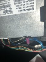
I'm just telling you what I see in the diagram I have access to. The pinouts for each connector are attached below. You can see they have the same circuit number and description there.
Diagrams are sometimes dependent on vehicle configuration. Obviously your vehicle isn't configured to have the VCIM spliced into pin C of that splice pack, but since my diagram shows an alternate method, perhaps that is how yours is wired. That's why I suggested you perform a continuity check on the circuit to verify. I have attached the wiring diagram below. You will notice it shows both configurations in my diagram. Obviously only one is correct.


