Great buy and likely at a price lower than any visit to the dealer for a diagnosis. And when looking at the waveform you can tell whether your LAN is working or not. Even where these situations are intermittent, it still tells you the story and gets you to the problem module quicker than any other that I know of. And the Onstar modules are known to be a module that causes problems. No module is immune, of course.
Module confusion and issues on my 2008 LMM
- Thread starter Dean E
- Start date
You are using an out of date browser. It may not display this or other websites correctly.
You should upgrade or use an alternative browser.
You should upgrade or use an alternative browser.
Looks like I spoke too soon. Took the truck this morning and as I was going down hill to the hwy the truck became possessed again! I turned around and went back home and hooked up a OBD2 pin out box and my new Uscope. By the time I got things connected the trucked cleared out the buss issues!Great buy and likely at a price lower than any visit to the dealer for a diagnosis. And when looking at the waveform you can tell whether your LAN is working or not. Even where these situations are intermittent, it still tells you the story and gets you to the problem module quicker than any other that I know of. And the Onstar modules are known to be a module that causes problems. No module is immune, of course.
Well now with my truck cab looking like a science experiment the issue reappeared at lunchtime with a vengence. The GMLAN goes low (zero) when the buss if failing. So either a bad module or wiring grounding out. I still have the lower center dash panel removed and wiggling the wires going to the On Star module does seem to make a difference but removing the connectors did not clear the problem. Wiring, maybe. I will go into the splice pack and connect the test harness to confirm the wiring to the On Star module. According to the wiring prints this comes in on pin C of the splice pack but also jumpers off to an Module-Export. D-386 page 25 of 30. Not sure that other module would be on my truck. So removing jumper on pin C of the pack should confirm the problem. Making headway. I should have purchased these items sooner. It surely is a learning experience. DeanGreat buy and likely at a price lower than any visit to the dealer for a diagnosis. And when looking at the waveform you can tell whether your LAN is working or not. Even where these situations are intermittent, it still tells you the story and gets you to the problem module quicker than any other that I know of. And the Onstar modules are known to be a module that causes problems. No module is immune, of course.
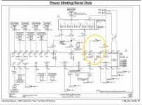
Yes that is the pin C I was referring to. I just was not sure on this export module. Saturday I will go out and remove the comb from the splice pack and install the jumper harness. The end of that jumper harness has a connection for a probe lead. I will mark each pin (especially C) so the next time the system acts up I can pull that jumper first and see if the communication on the buss comes back. DeanI think that the pin C feeds something for export vehicles (not yours), but also notice that it feeds Onstar. Follow pin C up and to the right.
Well I managed to get the splice TS harness in the splice saver. It is a 12 pin comb and noticed I have two pins with no wiring in them. C and K. Per the wiring manual that Ron put out there the pin C is for the OnStar and K is for infotainment stuff that my SLE would not have. I understand not having anything in K but I do have an OnStar box on my truck and the rear view mirror with the OnStar controls on it. Am I missing something? The harness is installed and of course everything is working. The oscilloscope shows a good 7 volt reference. I did try removing one circuit at a time and naturally the truck instrument panel really lights up with the IPC disconnected which it to be expected. Like I stated before when the truck started acting up the oscilloscope went to 0,
Last time the truck acted up I had the center dash closeout panel removed for the OnStar. Removing J1 or J2 did nothing for the issue and the oscilloscope still showed 0 but wiggling the wires at the J1 and J2 did seam to bring the databuss back for a bit. Oddly enough wiggling the wires on J1 and J2 would not induce the problem so this really has me scratching my head as to why there is nothing on pin C of the splice saver. Dean
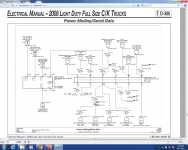
Last time the truck acted up I had the center dash closeout panel removed for the OnStar. Removing J1 or J2 did nothing for the issue and the oscilloscope still showed 0 but wiggling the wires at the J1 and J2 did seam to bring the databuss back for a bit. Oddly enough wiggling the wires on J1 and J2 would not induce the problem so this really has me scratching my head as to why there is nothing on pin C of the splice saver. Dean

Well here is the latest. I could see the serial buss come back to life when wiggling the wires to the On Star module just below the HVAC controls. I have everything wired in with the breakout harness to capture the event again but so far nothing has failed again. I did have one day the truck spooked me. It appeared the batteries were getting weak and when I tried to start the truck the starter engaged and then disengaged but it did crank very slow. The truck started on the second attempt but as before it cranked pretty slow and once started I now had a check engine light. I threw the code reader in the cab and started off to work. When I got down on the main hwy the truck was in limp mode but the check engine light was not flashing! I cleared out the codes and started out. The check engine light was not on anymore but the truck did not run right. Very weak on power and had some light black smoke when I got into the throttle a bit. The check engine light did not come back on. Made it to work and during lunch I started the truck again and everything seemed fine. On the way home I looked at turbo vane command and position along with rail pressures and everything looked fine. On the ride home everything seemed normal. No idea what had happened.
I was speaking with another member who was having a similar databus issue and his ended up being the wheel speed wiring for the ABS. Now here is where I am scratching my head. Take a look below
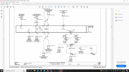
According to the print pin 19 is the low speed databuss connection to the system. I have checked on the BCM wiring and can not find where this wire goes to on the BCM. This is the closest I can find.
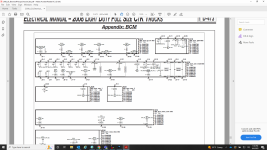
Granted I am used to using aircraft wiring prints and tracking wires down on auto stuff is not what I am used to. Like I stated before, when the issue reared it ugly head the last time I could wiggle the harness at the VICM (On Star) module and the databuss would come active again but to my dismay the wiring for the splice saver shows the low speed buss wire that is for the On Star is on pin C of the splice saver. I have no wire at pin C at the splice saver.
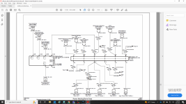
Needless to say, I'm having some difficulty understanding how this is all laid out. The batteries are about 4 years old and not holding a charge for very long. About 4 days and the starter can barely crank the engine. I will be getting new batteries before the week is over. Dean
I was speaking with another member who was having a similar databus issue and his ended up being the wheel speed wiring for the ABS. Now here is where I am scratching my head. Take a look below

According to the print pin 19 is the low speed databuss connection to the system. I have checked on the BCM wiring and can not find where this wire goes to on the BCM. This is the closest I can find.

Granted I am used to using aircraft wiring prints and tracking wires down on auto stuff is not what I am used to. Like I stated before, when the issue reared it ugly head the last time I could wiggle the harness at the VICM (On Star) module and the databuss would come active again but to my dismay the wiring for the splice saver shows the low speed buss wire that is for the On Star is on pin C of the splice saver. I have no wire at pin C at the splice saver.

Needless to say, I'm having some difficulty understanding how this is all laid out. The batteries are about 4 years old and not holding a charge for very long. About 4 days and the starter can barely crank the engine. I will be getting new batteries before the week is over. Dean
I looked up the wiring in prodemand, and it shows the VCIM is connected to the splice pack JX221 at PIN J via the left I/P junction block and possibly through another splice pack in the instrument panel harness behind the dash depending on radio/infotainment options. You can verify that with a continuity test between pin J and pin 1 of the VCIM X1 connector.Well I managed to get the splice TS harness in the splice saver. It is a 12 pin comb and noticed I have two pins with no wiring in them. C and K. Per the wiring manual that Ron put out there the pin C is for the OnStar and K is for infotainment stuff that my SLE would not have. I understand not having anything in K but I do have an OnStar box on my truck and the rear view mirror with the OnStar controls on it. Am I missing something?
I was just going to respond to my own question. I did find that, takes a few pages to get there. The diagram at the front of the databus section is a bit misleading as to what is on the splice saver. The BCM is showing on the splice saver but it looks like the ABS stuff reports directly to the BCM and not thru the splice saver.
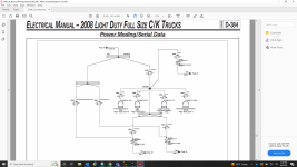
Guess I will need to look at this SB5986. Thanks, Dean
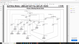
According to my diagrams, that wire goes to pin 19 in the X3 connector of the BCM, but I'm not sure that will have anything to do with your communication problem since it is a different circuit from the one on which you are seeing the comm failure.According to the print pin 19 is the low speed databuss connection to the system. I have checked on the BCM wiring and can not find where this wire goes to on the BCM. This is the closest I can find.
Yes, I have printed it out and looking at the wiring. I am curious on what the difference is between the light blue serial data com enable and the dark blue acc serial wake up serial data? Deanhave you looked at the PDF of the LMM data lines from post #2 yet? that will tell you where each line runs into each module, wire color and pin number
Not sure how? The X3 pin 19 is the low speed serial data enable buss. DeanAccording to my diagrams, that wire goes to pin 19 in the X3 connector of the BCM, but I'm not sure that will have anything to do with your communication problem since it is a different circuit from the one on which you are seeing the comm failure.
This is what I see in the prints. J1pin 1 which goes directly to the splice saver. Am I missing something? DeanI looked up the wiring in prodemand, and it shows the VCIM is connected to the splice pack JX221 at PIN J via the left I/P junction block and possibly through another splice pack in the instrument panel harness behind the dash depending on radio/infotainment options. You can verify that with a continuity test between pin J and pin 1 of the VCIM X1 connector.
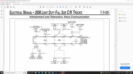
What is on page 1 of this? Deanhave you looked at the PDF of the LMM data lines from post #2 yet? that will tell you where each line runs into each module, wire color and pin number
I don't understand your question. the PDF I posted on page one of this thread. post #2. it has the breakdown of all the data lines, splice points, locations, colors, pin numbers, etcWhat is on page 1 of this? Dean
The page you sent showed 2 of 2 pages. I was just curious on what was on the first page. DeanI don't understand your question. the PDF I posted on page one of this thread. post #2. it has the breakdown of all the data lines, splice points, locations, colors, pin numbers, etc
ah ok. I have no idea. it was originally posted by another member and I just reposted it here.The page you sent showed 2 of 2 pages. I was just curious on what was on the first page. Dean


