LMM code U0073?

Mogman

Member
May 3, 2020
341
17
18
Papalote, TX
Has anyone had a U0073 "communications bus off" after installing a Duramax with a stand alone harness?
After doing some reading it appears to possibly be a resistance issue because of the missing BCM/GP controller etc.
I measure 120 ohms on the serial bus which is what I would think would be correct, tried loading it down more with 120 ohm resistor, still no love.

EDIT, I found the glow plug controller and plugged it in (I had bypassed the bus on that plug so I could read/write to the ECM) still getting the U0073 code.

I can read/write to the ECM and TCM, the T/C shift control is obviously in communications because when I write to the ECM the front shift motor goes through some cycles
 
Last edited:

Jakezed22

Active member
Dec 2, 2016
256
125
43
Does your can bus have a terminating resistor at the opposite end of the ecm on the bus?
 

Mogman

Member
May 3, 2020
341
17
18
Papalote, TX
Thanks for the reply, I will have to see if I can see on the prints what is terminated to what, I have a ECM, TCM and TCCM along with the DLC on that bus.
I do see 120 ohms on the bus so there is a termination somewhere, I also tried loading down the bus with another 120 ohms did not work.
It would be nice to find a complete bus schematic, all I get is bits and pieces from the alldata sight.

I only see one GMLAN bus (pins 44 and 57) on the ECM so I do not understand what you mean buy the "opposite end" unless you mean the DLC then yes I did try terminating that end.
 

kidturbo

Piston Tester
Jul 21, 2010
2,539
1,375
113
Somewhere On The Ohio
www.marinemods.us
The ECM has 120 ohms terminator built in by default. The other one can be placed anywhere on the bus. Check across the CAN-HI and CAN-LO wires, you should read 60ohm or close to it.
I don't think that's your problem however. I've played with that particular ECM on the bench more than anyone and don't recall that particular code.


Mogman

Member
May 3, 2020
341
17
18
Papalote, TX
The ECM has 120 ohms terminator built in by default. The other one can be placed anywhere on the bus. Check across the CAN-HI and CAN-LO wires, you should read 60ohm or close to it.
I don't think that's your problem however. I've played with that particular ECM on the bench more than anyone and don't recall that particular code.

I may have started with a crap tune, you never know what you are really getting when you download a tune from a library, I was working with a guy to try and get the idle to not sound so choked off and the files in my tune did not all jive with the guy helping me LMM files so when I get a chance I am going to start over with a tune I found that did jive with the guys tune, it may take a few days
 

2004LB7

Well-known member
Dec 15, 2010
6,990
2,146
113
Norcal
There should be a 120 ohm resistor on each end of the bus. As Ken stated, there is one at the ecm. I think the glow plug controller has the other. Since you removed it you will have to add a 120 ohm resistor in it's place. The resistance between the high and low should be 60 ohms
 

Mogman

Member
May 3, 2020
341
17
18
Papalote, TX
I have re-installed the glow plug controller, I still measure 120 Ohms, I added a 120 Ohm resistor to the bus (with and without the glow plug controller installed) and it made no difference, I was a SCADA and communications technition for almost 40 years so I understand a little about serial buses, of course on the automotive side I am a total rookie.
I appreciate all the input and suggestions, think I am going to move on to some of the mechanical work left to get my state inspection and plates, after over 7 months I am ready to put some wheels on this thing and see it in the sunlight again!!. meanwhile I am going to build another tune using a different "stock" tune.
I will report back after trying the different tune.
 

Cougar281

Well-known member
Sep 11, 2006
1,809
253
83
St Louis, MO
If you're seeing 120 Ohms across the GMLAN+ and GMLAN- lines, something's wrong. You should have 60 Ohms if it's properly terminated.

In looking at the schematics, the path taken appears to be from the DLC to the 'X2' connector in the left I/P junction block, where it splits and goes to the VICM, then to the TCCM (If Onstar Equipped and 4x4, from the DLC to the TCCM if not Onstar Equipped and 4x4), then to the EBCM, then the TBCM (If equipped) and then to a 'Data Link Resistor'. The other 'branch' taken from the split at the X2 connector is to the BCM, then the GPCM, then to the PTO module if equipped, then to the TCM, and then to the ECM where it's terminated internally. All of the devices in the chain must be present or the GMLAN data lines jumped because they enter the modules in one set of pins and exit through another (It's not like CLass2 or Low Speed GMLAN where modules are just spliced in). So basically, the ECM is one end of the termination and the other is on the 'other side' of the X2 connectors splice of the GMLAN+ and GMLAN- wires, after the VICM, TCCM, EBCM and TBCM. If none of those modules are present, then it probably should be terminated where the DLC lines join with the lines heading to the BCM.
 

Attachments

  • LMM Data Lines.pdf
    85.2 KB · Views: 16
  • Like
Reactions: Mogman and 2004LB7

kidturbo

Piston Tester
Jul 21, 2010
2,539
1,375
113
Somewhere On The Ohio
www.marinemods.us
The second 120ohm terminator was in the chassis harness near the rear bumper on LBZ/LMM trucks.. I never could figure out why they put it back there. Guess some bus chassis or something had a CAN module towards rear axle. But once again, that shouldn't cause the code. In stand alone setups, I typically put a resistor on back of the DLC plug. Starting with a fresh tune file sounds like a good plan.

Couple other things ya might check. Make sure the MIL is actually working as you l expect. I used some cool LED MIL's and found the pull up resistor on the ECM circuit actually passes enough power to illuminate the bulb dim when it should be off. See pic below, the lights are actually off in this pic. So use EFIlive control to test your bulb on and off modes.

Second, single serial bus wire [blue] needs to be tied in with the ECM power wires. Guessing you've done that since you've loaded tunes before. My experience is if not provided power at key on, when loading tunes, it will brick the ECM. So I always tie it into the power wires and never an issue.

20210211_182942.jpg
 
  • Like
Reactions: Mogman

TheBac

Why do I keep doing this?
Staff member
Apr 19, 2008
15,611
1,868
113
Mid Michigan
One of you guys needs to draw up a diagram of what you're talking about.....

Its funny, when I was installing the Nav unit in the Aurora years ago, I always wondered why there were two bus wires at every connector. Now I know....
 

Cougar281

Well-known member
Sep 11, 2006
1,809
253
83
St Louis, MO
One of you guys needs to draw up a diagram of what you're talking about.....

Its funny, when I was installing the Nav unit in the Aurora years ago, I always wondered why there were two bus wires at every connector. Now I know....
The pdf I attached has the stock diagram from module to module.

And on the LMM, the TBCM is on the frame rail behind the fuel tank, so that's why the terminating resistor is there.

Sent from my Pixel 5 using Tapatalk
 

kidturbo

Piston Tester
Jul 21, 2010
2,539
1,375
113
Somewhere On The Ohio
www.marinemods.us
I knew there had to be a module back there somewhere. All this advice coming from a guy who's never owned a Duramax powered truck.. I have chop shopped a few however. LOL

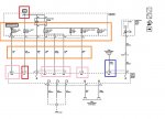
Here is my ECM power wiring diagram I've used for years. Noticed the D-BU Serial Data wire lists IGN on the ECM connector side. Lot of people miss that one when wiring up a stand alone harness. But the ECM tends to freaks out if you do. If I recall correctly, the BCM sends a 12v signal via that wire to wake ECM up. Then all your key on and start commands are HS-GMLAN data from BCM to ECM, and ECM kicks in the PTR and Start relays. In stand alone, we kinda wire it up backwards and luckily the ECM doesn't mind and fires on a crank/cam signal without knowing it's cranking..

ECM_Power_Fuses.jpg
 

Mogman

Member
May 3, 2020
341
17
18
Papalote, TX
The reason load resistors are used on serial buses is to make the circuit appear to be low impedance, low impedance circuits are less subject to being influenced by external electromagnetic interference, it makes perfect sense to put a load resistor at the for end of a long line to be sure that line has the low impedance protection. The MIL light appears to be working correctly as it goes out when all the codes are erased, until another U0073 code is generated
 

Mogman

Member
May 3, 2020
341
17
18
Papalote, TX
Well,,, I was using my trusty old Autel to read the codes, all it showed was the U0073, switched to the EFILive box and it shows some TCM codes, may be why I am bumping my head here, the Autel showed TCM codes before when I had a bad return in the harness for the temp and Mode sensor so I am baffled as to why all of a sudden it will not read the TCM codes, so tomorrow I am going to pull the TCM and do the deletes as if it was a stand alone without the Allison and if I am finally heading in the right direction the codes should all go away.
The codes I am reading now are C0569, P0218, P0088 and U0073, I think the first one is the transfer case controller.