LB7: How to size a water pump and radator for a water to air intercooler

MAXX IT OUT

<<<IT WORKS
Mar 1, 2013
1,781
39
48
Des Moines, Iowa
Well since i broke my leg and can't drive my truck anymore i was thinking about hooking up my water to air intercooler. If i knew how much heat i was dealing in BTU's i could figure it out, but i want to pick your brains. Is to big of a heat exchanger as bad as to small of one and the same with the flow of the pump. Any help would be appreciated.
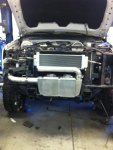
This is what the setup was like and i will be modifying it some more to work with my truck.
 

Attachments

  • image4.jpg
    image4.jpg
    191.2 KB · Views: 81
Last edited:

Duramax One

Vote for Pedro
Aug 11, 2012
140
0
16
Oroville, CA
Properly designing an efficient system can get really complicated really quickly. There are quite a few things you need to know in order to size your system. If you did know how much heat you were attempting to remove it would make it much easier. Without knowing that, you basically have to rely on assumptions and rough estimates.

For laughs, you could calculate the heat induced purely by the compression of air by your turbo (assuming an adiabatic process because we don't know how much heat is transferring through your turbo). This will give you a very rough, first-step approximation for the approximate size of components you will need.

You can rearrange the ideal gas law to output a temperature, which can later be plugged into the heat transfer equation Q=hA(T1-T2) in order to determine your heat added (Q) in Watts. Of course, you need to calculate your heat transfer coefficient, h, which is complicated when dealing with flow through pipes and a heat exchanger. But, hey, we're making assumptions here anyway, right?

Rearranging the ideal gas law PV=nRT to solve for temperature gives us (PV)/(nR) = T. Since you need to calculate T1 (pre-turbo) and T2 (post-turbo) you get two equations. It is important to note that n is the amount of air in moles and R is the ideal gas constant. The amount of air (n) remains constant after passing through the turbo. R is constant by definition.

Equation 1
(P1V1)/(nR) = T1
where V1 is the volume of air before being compressed and P1 is absolute atmospheric pressure.

Equation 2
(P2V2)/(nR) = T2
where V2 is the volume of air after being compressed and P2 is your absolute boost pressure

Solving for deltaT = (T1-T2) gives us deltaT = (P1V1)/(nR) - (P2V2)/(nR). This can be plugged in to the heat transfer equation to calculate for the amount of heat introduced to the air by compression.

Rewriting the heat transfer equation gives you Q = hA[(P1V1)/(nR) - (P2V2)/(nR)]. Here A is the surface area that the fluid is in contact with.

Solving for Q will give you a very rough estimate of the adiabatic heat introduced by compression. This Q is the same amount of energy you ideally want to remove using your air-to-water intercooler, therefore it is the same amount of heat you need to remove from your intercooler's radiator.

As far as sizing your radiator and pump goes... well, it's complicated as well. Once you know the amount of heat you are dealing with, you can size a radiator based on your estimated airflow, air temperature, and the amount of heat being removed. The efficiency of the radiator is one of the largest factors that impacts the size required. I don't remember any of the radiator/fin cooling equations off the top of my head.

Once you have sized the radiator, you need to select a pump for the correct volumetric flow rate. Basically, if you push the water through the radiator too quickly you are not going to remove the correct amount of heat. Too slowly and you don't get enough flow through the intercooler to chill the charge air. You'll have to find pump curves for the different pumps you are looking at and try to match the flow and head loss to your requirements.
 

DAVe3283

Heavy & Slow
Sep 3, 2009
3,729
297
83
Boise, ID, USA
If we could get a log of boost and MAF (real MAF, which means it must be calibrated for aftermarket intakes, not faked like most tuners) that would help a lot.

Even if you just know peak boost and peak MAF rate that would help. But again, it must be real airflow values, not a compromised rescale of the sensor.
 

Duramax One

Vote for Pedro
Aug 11, 2012
140
0
16
Oroville, CA
Not having any thermodynamics or fluid systems textbooks in front of me, I can't recall if under forced convection (which we have) if the equation is Q=hA(T1-T2) or if it is Q=hA[(T1^4)-(T2^4)]. I seem to recall the latter, but I am not positive.
 

lts1ow

Needs moar PAH!
May 14, 2012
1,598
0
36
NJ
What size are the feed lines for the coolers? I would make em 1 inch or larger and run the biggest pump you can find.
 

WolfLMM

Making Chips
Nov 21, 2006
4,005
26
48
38
AL
Properly designing an efficient system can get really complicated really quickly. There are quite a few things you need to know in order to size your system. If you did know how much heat you were attempting to remove it would make it much easier. Without knowing that, you basically have to rely on assumptions and rough estimates.

For laughs, you could calculate the heat induced purely by the compression of air by your turbo (assuming an adiabatic process because we don't know how much heat is transferring through your turbo). This will give you a very rough, first-step approximation for the approximate size of components you will need.

You can rearrange the ideal gas law to output a temperature, which can later be plugged into the heat transfer equation Q=hA(T1-T2) in order to determine your heat added (Q) in Watts. Of course, you need to calculate your heat transfer coefficient, h, which is complicated when dealing with flow through pipes and a heat exchanger. But, hey, we're making assumptions here anyway, right?

Rearranging the ideal gas law PV=nRT to solve for temperature gives us (PV)/(nR) = T. Since you need to calculate T1 (pre-turbo) and T2 (post-turbo) you get two equations. It is important to note that n is the amount of air in moles and R is the ideal gas constant. The amount of air (n) remains constant after passing through the turbo. R is constant by definition.

Equation 1
(P1V1)/(nR) = T1
where V1 is the volume of air before being compressed and P1 is absolute atmospheric pressure.

Equation 2
(P2V2)/(nR) = T2
where V2 is the volume of air after being compressed and P2 is your absolute boost pressure

Solving for deltaT = (T1-T2) gives us deltaT = (P1V1)/(nR) - (P2V2)/(nR). This can be plugged in to the heat transfer equation to calculate for the amount of heat introduced to the air by compression.

Rewriting the heat transfer equation gives you Q = hA[(P1V1)/(nR) - (P2V2)/(nR)]. Here A is the surface area that the fluid is in contact with.

Solving for Q will give you a very rough estimate of the adiabatic heat introduced by compression. This Q is the same amount of energy you ideally want to remove using your air-to-water intercooler, therefore it is the same amount of heat you need to remove from your intercooler's radiator.

As far as sizing your radiator and pump goes... well, it's complicated as well. Once you know the amount of heat you are dealing with, you can size a radiator based on your estimated airflow, air temperature, and the amount of heat being removed. The efficiency of the radiator is one of the largest factors that impacts the size required. I don't remember any of the radiator/fin cooling equations off the top of my head.

Once you have sized the radiator, you need to select a pump for the correct volumetric flow rate. Basically, if you push the water through the radiator too quickly you are not going to remove the correct amount of heat. Too slowly and you don't get enough flow through the intercooler to chill the charge air. You'll have to find pump curves for the different pumps you are looking at and try to match the flow and head loss to your requirements.


Just a quick question, I was under the assumption that, water in a cooling system could *never* flow across a surface too quickly as to reduce cooling. I understand a cooling system has a finite limit to the amount of heat it can remove. But, I didn't think cooling water could ever flow too quickly in a system to negatively impact efficiency?
 

LWATSON

future trans limpers
Jul 30, 2008
2,587
1
36
55
Scotland Neck NC
Just a quick question, I was under the assumption that, water in a cooling system could *never* flow across a surface too quickly as to reduce cooling. I understand a cooling system has a finite limit to the amount of heat it can remove. But, I didn't think cooling water could ever flow too quickly in a system to negatively impact efficiency?
I'm with you on this one, the faster the water moves the better it will cool. When you talk about coolant flowing through a radiator its a whole different ballgame.
 

DAVe3283

Heavy & Slow
Sep 3, 2009
3,729
297
83
Boise, ID, USA
In something restrictive like a radiator, the back pressure will probably prevent the water from moving too quickly to remove heat. For things like an engine head, with large open passages, you can end up with currents where the water in the center moves right through and the water at the boundary doesn't move much at all. Kind of like a river. Engines solve this with the thermostat(s), which limit flow rate. I've had older engines overheat when run without thermostats, but run ice cold with them installed.

But for this setup, there is probably no practical upper limit to the pump size. At some point it will just start creating back pressure.
 

Cougar281

Well-known member
Sep 11, 2006
1,820
259
83
St Louis, MO
If we could get a log of boost and MAF (real MAF, which means it must be calibrated for aftermarket intakes, not faked like most tuners) that would help a lot.

Even if you just know peak boost and peak MAF rate that would help. But again, it must be real airflow values, not a compromised rescale of the sensor.

Not sure what you mean by 'fake MAF' - unless there's some strange monkey business going on, if the orifice that the MAF is sitting in has a different cross-section than stock, the MAF tables would have to be re-calibrated or else the truck won't run right - if the ECM thinks it's getting 'X' g/sec but it's actually getting 'Y' g/sec, it's not going to run right - you'll either get smoke due to not enough air for a proper burn or you're not going to get enough fuel for the air being drawn in. If the orifice has the same cross-section as the stock one, then the MAF reading will be correct and the rest of the intake plumbing doesn't really matter for the purposes of MAF measurement. Any company that sells an intake along with a tuner that doesn't properly rescale the MAF tables for the intake but instead does some monkey business and goofs with the MAF signal (or disables it) shouldn't be selling a product IMO.
 

DAVe3283

Heavy & Slow
Sep 3, 2009
3,729
297
83
Boise, ID, USA
Not sure what you mean by 'fake MAF' - unless there's some strange monkey business going on, if the orifice that the MAF is sitting in has a different cross-section than stock, the MAF tables would have to be re-calibrated or else the truck won't run right - if the ECM thinks it's getting 'X' g/sec but it's actually getting 'Y' g/sec, it's not going to run right - you'll either get smoke due to not enough air for a proper burn or you're not going to get enough fuel for the air being drawn in. If the orifice has the same cross-section as the stock one, then the MAF reading will be correct and the rest of the intake plumbing doesn't really matter for the purposes of MAF measurement. Any company that sells an intake along with a tuner that doesn't properly rescale the MAF tables for the intake but instead does some monkey business and goofs with the MAF signal (or disables it) shouldn't be selling a product IMO.
The MAF reads a fraction of the airflow through the intake. When you go to a larger intake, the MAF needs rescaled.

I've seen several tunes where the MAF sensor is not scaled right (or at all) for a larger intake. Instead the MAF limiter tables are modified to get the desired effect. This works just fine, actually. That is why I say the tune can't have a 'fake' MAF scaling.
 

LB7 Lover 1994

Know Nothing
Jul 20, 2013
262
0
16
Greene County, In
At the end of classes this semester one of our instructors was telling us that coolant flowing to fast will not cool as well as you would think. It has to be able to stay in the radiator long enough for the fan to be able to pull cold air through the radiator and pull heat off of the coolant.
 

Cougar281

Well-known member
Sep 11, 2006
1,820
259
83
St Louis, MO
The MAF reads a fraction of the airflow through the intake. When you go to a larger intake, the MAF needs rescaled.

I've seen several tunes where the MAF sensor is not scaled right (or at all) for a larger intake. Instead the MAF limiter tables are modified to get the desired effect. This works just fine, actually. That is why I say the tune can't have a 'fake' MAF scaling.

Of course that only applies if the cross section of the portion that the MAF is sitting in was actually changed as well - If we were talking about an intake that only changed the piping from the MAF housing to the turbo, it wouldn't make a difference