fuel cell and sending unit wiring
- Thread starter dracing70
- Start date
You are using an out of date browser. It may not display this or other websites correctly.
You should upgrade or use an alternative browser.
You should upgrade or use an alternative browser.
I literally just swapped a sending unit in my truck. It is ohms. Voltage in the fuel tank?
I'd like to see a screen shot of these voltage tables. Not saying y'all are lying but it just sounds crazy.
Just as many sensors work, the sending unit applies different resistance to the 5 volt reference signal depending on how full the tank is. The computer then sees different voltages based on the tank level. The problem is the sending unit in this fuel cell is 0-90 ohms, so with stock tuning we're barely on the map with the new unit and a full tank.
Correct, the computer is comparing the return voltage off the 5V reference signal. As the resistance (ohms) varies, the voltage the computer sees varies.
You need to hook up your V2, and log the fuel sender voltage PID. Look at what the ECU is reading for voltage.
I rescaled mine to be more accurate using the same technique. Start with an empty tank. Record the voltage. Add 1 gal, wait for the fuel to stop sloshing (might not apply to a fuel cell). Record the voltage. Repeat until full.
Once you have a nice chart of voltage to fuel level, then you copy those into your ECU table. Use the linear interpolation tool between the data points, and you are done!
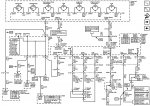
Thanks for all the tips guys. Do you think I have it wired properly though ?? Does the black just get grounded and the purple go to the signal terminal on top of the sending unit???
Correct, the computer is comparing the return voltage off the 5V reference signal. As the resistance (ohms) varies, the voltage the computer sees varies.
You need to hook up your V2, and log the fuel sender voltage PID. Look at what the ECU is reading for voltage.
I rescaled mine to be more accurate using the same technique. Start with an empty tank. Record the voltage. Add 1 gal, wait for the fuel to stop sloshing (might not apply to a fuel cell). Record the voltage. Repeat until full.
Once you have a nice chart of voltage to fuel level, then you copy those into your ECU table. Use the linear interpolation tool between the data points, and you are done!
The black is a low reference signal. It is ground, but should be a separate signal back to the ECU. It should connect to the sending unit case/housing. The purple does go to the terminal on the sending unit.Thanks for all the tips guys. Do you think I have it wired properly though ?? Does the black just get grounded and the purple go to the signal terminal on top of the sending unit???
.jpg")
If you just ground the black wire somewhere, it will cause your fuel level reading to be erratic, or not work at all. The black wire MUST connect to the other side of the fuel level sensor. This is usually the metal mount plate on most aftermarket sensors.
Attachments
On top of the sending unit it should have came labeled for the ground and the signal. Black to ground and purple to signal.
The black is a low reference signal. It is ground, but should be a separate signal back to the ECU. It should connect to the sending unit case/housing. The purple does go to the terminal on the sending unit.
View attachment 33237
If you just ground the black wire somewhere, it will cause your fuel level reading to be erratic, or not work at all. The black wire MUST connect to the other side of the fuel level sensor. This is usually the metal mount plate on most aftermarket sensors.
Ok so the spade connector on the attached to the sending unit housing directly is correct. Thanks