Compressor Efficiency Problem

Diesel Pilot

Hat? Suitcase? 50 BMG?
Aug 9, 2006
1,424
0
36
47
Pickerington, OH
100% agree Johnboy. The VVT turbo does lose out a bunch at higher rpm, external gate would be something cool to try.

I'm going A

Reason: The compressor is designed to push, not pull. It's much more efficient for the compressor to push past a 2 psi block than pull through a 2 psi block.
 

Killerbee

Got Honey?
These are all great responses. Love the enthusiasm. Johnboy, those are interesting points, and great insight. I have also wondered why someone hasn't come up with a wastegated VGT. In search of explanations for the severe amount of apparent parasitic drag, I too would typically focus on exhaust restriction. Yet, something just kept telling me that the intake side of the turbo had something wrong with it. Afterall, high drive pressure just means the turbine is resistant, since it is shaft connected to the compressor, it is entirely possible that there is nothing on the exhaust side causing the problem. The dramatic COT's I have logged (as high as 590 F) on the compressor side were trying to tell me something, and I started to believe that they were related to a hidden induction flaw.

Going back a bit, it took me nearly 2 years to resolve that LLY overheating frequency (compared to the LB7) had nothing to do with its cooling system. Some are familiar with this effort. It was not an easy paradigm shift to get away from looking at things like radiator design, water pump cavitation etc, and start looking at other relationships.

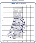
Anyway, this is a problem that involves looking at the compressor map. One objective of effective forced induction is to keep compressor efficiency as high as possible, for given airflow desires. This is important to turbo longevity, as well as optimizing compressed air density and temp. On the map, the things that affect efficiency are Pressure Ratio-PR, inlet air temp, and of course MAF. PR is defined as the COP/CIP. Elevation affects PR, by reducing CIP, compressor inlet pressure. The restriction improvement of 2 psi, for the purpose of this problem, affects Pressure Ratio, in 2 different ways, method A and method B. Compressor outlet/inlet pressure, absolute.

Use 36 (cop) and 12 (cip) psi for the baseline 3.00 PR. I am not using the ideal 34 (MAP) and 14 (atmospheric) because each side has 2 psi of losses. How does this PR number change with option A? Option B?

Remember, this is a hypothetical, the numbers are not real world, its a math problem for demonstration value.

Option A: increases CIP by 2 psi...36/14=2.57
Option B: decreases COP by 2 psi...34/12=2.83

FWIW, Diesel Pilot, that is the technical to your assertion, you are absolutely correct.

Each represents the same pressure at the MAP sensor, and both are better than 3.0, but clearly the one with the lowest PR, has the highest compressor efficiency, and that is key to:

1. reducing drive pressure, 2. reducing COT, 3. reducing induction heat production (induction overheating), 4. increasing plenum air density, 5. increasing economy, and a few other things

Option A has the highest performance value, pat yourselves on the back.

The point of this problem was to show just how much more important pre-compressor losses are to our goals, than post compressor losses, though both are significant. I am not a performance gearhead, I am a geek, but this argument applies equally to performance as well as the search for an overheat explanation. Go figure.
 

Attachments

  • Compressor Map.jpg
    Compressor Map.jpg
    60.4 KB · Views: 54
Last edited:

JOHNBOY

< Rocking the Big Single!
Aug 30, 2006
2,159
0
0
Saegertown, Pa
KB

Interesting. Diesel Pilot's explaination is a great one. Seeing temps like that makes me actually think that the copressor cover maybe the flawed peice. I have had some conversations with both Bullseye Power and Forced Inductions. Both are complete full service turbo shops. They cast housings, do machining and welding. Most turbo companies like HTT and II actually do not make there parts. One of the two companies I listed do it for them.

The shape and form of the cover can have a large effect on compressor performance. The guys from Forced told me that depending on the turbo rather suprising gains in both power and efficentency can be had with a properly designed race cover. These race covers have outlets that get bigger earlier and a larger over all volume to the passage. The inlet is also deeper and far less abrupt. More bell shaped. All this is said to really help move the air more efficently.

I do not have a LLY. I own a LB7 and LBZ. I am curious how the covers of the LLY and LBZ compare.

The routing of the CAC tubes on the LBZ is not as smooth or flowing as even the LLY or LB7. The tubes are suprising ly small IHMO. But this seems to both the LBZ little. That is what points me to the idea that the flaw could be the turbo compressor side itself.
 

JOHNBOY

< Rocking the Big Single!
Aug 30, 2006
2,159
0
0
Saegertown, Pa
Yes the LBZ tubes are 2.5" The tube from the turbo to the intercooler has a lot of bends to it. Like 4 45* and 1 75*. My LB7 tubes are 3" and far smoother in design. I will try to snap some pics tomorrow in the day light when it is aboe freezing.:rofl:
 

JOHNBOY

< Rocking the Big Single!
Aug 30, 2006
2,159
0
0
Saegertown, Pa
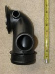
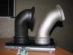
LB7 intake neck

IMGP0509_smaller.jpg
 

Killerbee

Got Honey?
we gotta move the intake riser!!! if we want bigger!

That is certainly one way to go. My temptation is too see how the much the mouthpiece can be improved, leaving the EGR/riser stock.

My initial assessment is that it can be appreciably improved. It is squeezed in there, but I see potential . Brandon and I discussed ideas.

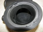
Todd, sent his mouthpiece to me for machining. It had been manually trimmed (from the factory) around the internal restricted areas. I am sure there are others like it. So some of these are better than others, though it probably represents only a mild improvement from the worst case, untrimmed ones.

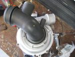
My sense is that the ball was dropped on the LLY intake. If anyone knows the part number to the LBZ counterpart, I will order one and look at it. This has me very curious now. I have Brandons LB7 mouthpiece, and it is without these issues.

To be clear, i am not talking about the riser. I am talking about this one. I started calling it a mouthpiece for some reason. One pic shows the LB7 mouthpiece also. The LBZ is not shown. That is what I am interested in JB.
 

Attachments

  • IMG_0255.jpg
    IMG_0255.jpg
    188.4 KB · Views: 148
  • IMG_0239.jpg
    IMG_0239.jpg
    64.2 KB · Views: 157
  • IMG_0244.jpg
    IMG_0244.jpg
    113.1 KB · Views: 87
  • IMG_0269.jpg
    IMG_0269.jpg
    86.5 KB · Views: 112
Last edited:

JOHNBOY

< Rocking the Big Single!
Aug 30, 2006
2,159
0
0
Saegertown, Pa
well it's today so where are the pics?


The Steeler game is over so took some pics. But neither TDP or CompD are letting me upload them. Anybody reccomend a good website to upload pics to?

More bad luck. My LBZ turbo is leaking oil from inside the comp. housing. Oil all over the inside of the boot and intercooler tube!
 

Kat

Wicked Witch of the West
Aug 2, 2006
17,899
13
38
60
Norco, CA
The Steeler game is over so took some pics. But neither TDP or CompD are letting me upload them. Anybody reccomend a good website to upload pics to?

Are they to big to post as attachments here? If you want you can e-mail them to me [email protected]


More bad luck. My LBZ turbo is leaking oil from inside the comp. housing. Oil all over the inside of the boot and intercooler tube!

:(
 

JOHNBOY

< Rocking the Big Single!
Aug 30, 2006
2,159
0
0
Saegertown, Pa
I sized them so they should not be to big for loading on the DP. But still no luck. I load one pic to CompD last night. The intake neck. They have no size limit as far as I know. I have some large pics there.


I my way into work I was thinking about the oil in the turbo. I hoping it is the PCV. I need to do the PCV reroute and see if that cures it.
 

LBZ

Super Moderator
Staff member
Jul 2, 2007
9,903
149
63
46
B.C.
I did the reroute after 15 000 miles. When I pulled the one intercooler pipe out, post intercooler, it had oil inside of it already. So that oil is all through the intercooler as well as the turbo.

Simon has some pics of the inside of the pipe I believe and ya it's gross.

I too would like to see a straighter, cleaner run into the turbo, as well as fewer bends and maybe larger pipe.
However, what sort of problems would larger tubes bring on? More volume to pressurize = more lag in the time it takes to build boost???? Would a drop in the velocity of the charge air cause other problems due to the larger piping?

IMO I don't see an advantage in larger piping as we are still limited by the restrictions in the rest of the plumbing I.E. the tiny gay designed Y-Bridge as well as the inlet/outlet to the tubo itself right??

I think redesigning the entire intake and exhaust system, starting from scratch is the expensive, but best direction we can take here. Maybe the sideways mounted turbo would give us more options...............

I wish I could draw because I have a picture in my mind of what I think an ideal set-up would look like.
 

Killerbee

Got Honey?
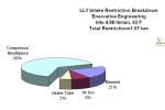
Reducing restriction on the cold side of the compressor, will benefit spoolup time in a big way.

Adding volume to the hot sides does, as you say, affect spoolup, as it becomes a larger air "spring". But I have so far found the modification to the cold side more than compensates for that, and the net result is a lower rpm turbo, that runs cooler, and at the correct PR.

It has been long accepted that 30-32 psi was the most boost that usefully produced power. With these changes, my belief is that will change to around 36. I feel it will be fair to say, nobody has ever seen the potential in the LLY, while running the stock compressor mouthpiece/elbow. The more tests I run on this piece the more convinced I am.

Just referring to the LLY here, haven't looked at the LBZ. I was surprised to see how much resistance came from the element, I have been a KN nazi for so long. I have had to change my position a little.

These proportions don't stay the same as MAF rises to 50+ lb/min. I'll let you all guess at where they shift.
 

Attachments

  • intake restriction breakdown-idle.jpg
    intake restriction breakdown-idle.jpg
    88 KB · Views: 129
Last edited: