Service Information
2006 Chevrolet K Silverado - 4WD | Sierra, Silverado VIN C/K Service Manual | Document ID: 2312651
#08-06-04-029C: LBZ, LLY, LMM MIL/SES Light On, DTC P0087-Fuel Rail Pressure (FRP) Too Low, Lack of Performance, No Power, Engine Runs Rough, No Start (Diagnose Fuel System Components) - (Jul 20, 2009)
Subject: LBZ, LLY, LMM MIL/SES Light On, DTC P0087– Fuel Rail Pressure (FRP) Too Low, Lack of Performance, No Power, Engine Runs Rough, No Start (Diagnose Fuel System Components)
Models: 2006–2007 Chevrolet Express, Kodiak C4500/C5500 Series, Silverado, Silverado Classic
2006–2007 GMC Savana, Sierra, Sierra Classic, TopKick C4500/C5500 Series
Equipped with 6.6L Duramax ™ Diesel Engine RPOs LBZ, LLY, LMM
Refer to GMVIS
Attention: Please check the vehicle repair order history to determine if a replacement fuel injection pump has already been installed for the above symptoms. If the fuel injection pump has been already replaced, then do not install another new fuel injection pump. The purpose of this bulletin is to aid technicians in the diagnosis and repair of fuel systems components on the Duramax™ Diesel Engine.
This bulletin is being revised to advise technicians that all parts are to be returned to the WPC. Please discard Corporate Bulletin Number 08-06-04-029B (Section 06 — Engine/Propulsion System).
Condition
Some customers may comment on an illumination of the MIL/SES with one or more of the following symptoms:
Lack of Performance
No Power
Engine runs rough
Lack of power
Vehicle may not start
Upon further investigation, the technician may find DTC P0087– Fuel Rail Pressure (FRP) Too Low stored in the ECM.
Cause
A ceramic high pressure valve ball fracture inside the fuel injection pump may lead to internal pump damage resulting in low fuel rail pressure. This condition may contaminate the common fuel rails and fuel injectors with debris. The fuel injection pump may operate, but with reduced output flow.
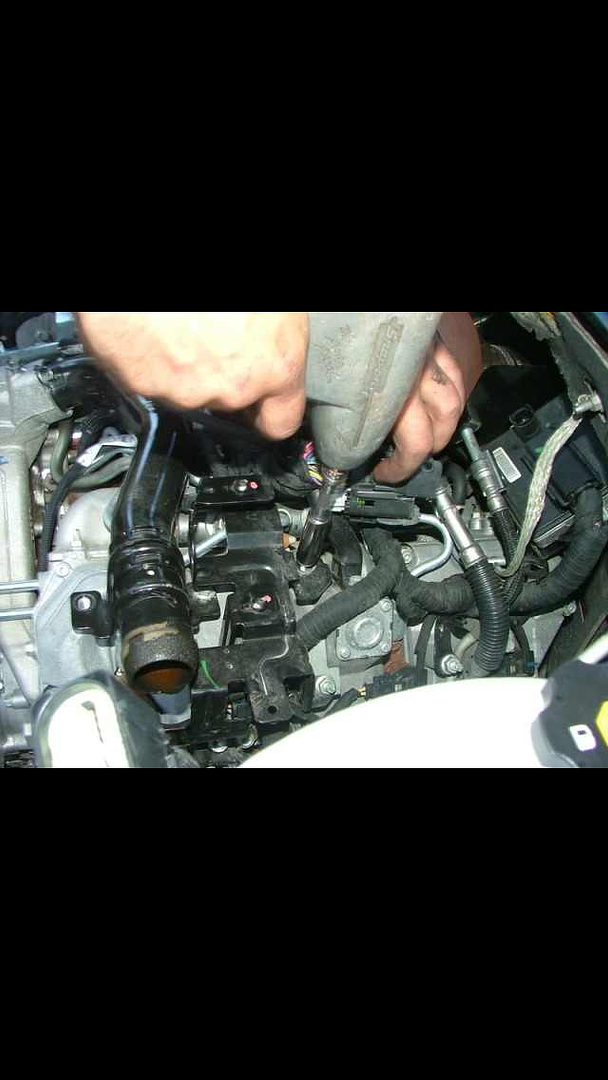
A high pressure valve fracture may cause the fuel injection pump cup plug (1) to come out, resulting in a no start condition and a possible fluid leak.
Bulletin Diagnostic Tips
There are several bulletin resources available in the Electronic Service Information System (SI) that can provide the technician with information on diagnosis and repair of the fuel system. Some of the bulletins available in SI include:
Information on Diesel Fuel Additives (Bulletin #03-06-04-017)
Information on Injector Bore Cleaning Kit (Bulletin #05-06-04-067)
Information on Servicing Fuel Injectors to Avoid Contamination (Bulletin #03-06-04-036)
Correction
Caution: Remove the fuel tank cap and relieve the fuel system pressure before servicing the fuel system in order to reduce the risk of personal injury. After you relieve the fuel system pressure, a small amount of fuel may be released when servicing the fuel lines, the fuel injection pump, or the connections. In order to reduce the risk of personal injury, cover the fuel system components with a shop towel before disconnection. This will catch any fuel that may leak out. Place the towel in an approved container when the disconnection is complete.
Important: Make sure you clock in and record the actual repair order clock time when completing this repair. A copy of the repair order and a print out of the Engine Data 1 snapshot along with the fuel rail pressure graph may be required. Failure to provide copies of this information may cause your warranty claim to be rejected.
Start by diagnosing the fuel system components by referring to Fuel System Diagnosis in SI.
If the vehicle starts and runs, verify that there are no fuel pump inlet restrictions on the supply side by inspecting for kinked fuel lines or a clogged fuel filter. If the vehicle does not exhibit any fuel supply restrictions or the engine does not start, proceed with the following diagnosis:
If the past repair order history shows the fuel injection pump was replaced, inspect the left fuel rail for debris and/or fuel contamination. It will be necessary to remove the fuel pressure relief valve to visually inspect inside the fuel rail. Refer to Fuel Pressure Relief Valve Replacement in SI.
If particle debris is found in the left fuel rail, perform Steps 12–19.
If no debris is found in the left fuel rail, install the fuel pressure relief valve and tighten. Perform the fuel injector return flow test by referring to Fuel Return System Diagnosis in SI.
Tighten
Tighten the fuel pressure relief valve to 100 Y (74 lb ft).
If the vehicle will not start and/or there is evidence of a leak coming from the fuel injection pump, inspect for a missing or damaged cup plug on the fuel injection pump. If a damaged cup plug is found, perform Steps 11–19.
If the fuel injection pump has not been previously replaced and there is no evidence that the cup plug is damaged, test the fuel injection pump for excessive fuel pressure fluctuations by following Steps 1- 10 below.
Start and idle the engine to normal operating temperatures.
Using a Tech®2 scan tool, build the vehicle information.
Select F2: Special Functions.
Select F2: Fuel Systems.
Select F3: Fuel Pressure Control.
Using the Tech®2 scan tool, increase the fuel rail pressure to 100 MPa (14,503 psi) for desired fuel rail pressure.
Tip: You will have to manually exit the snapshot after 1 minute of recording.
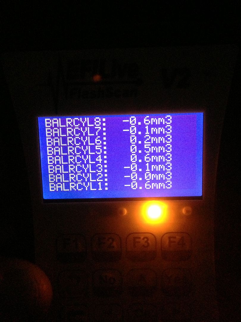
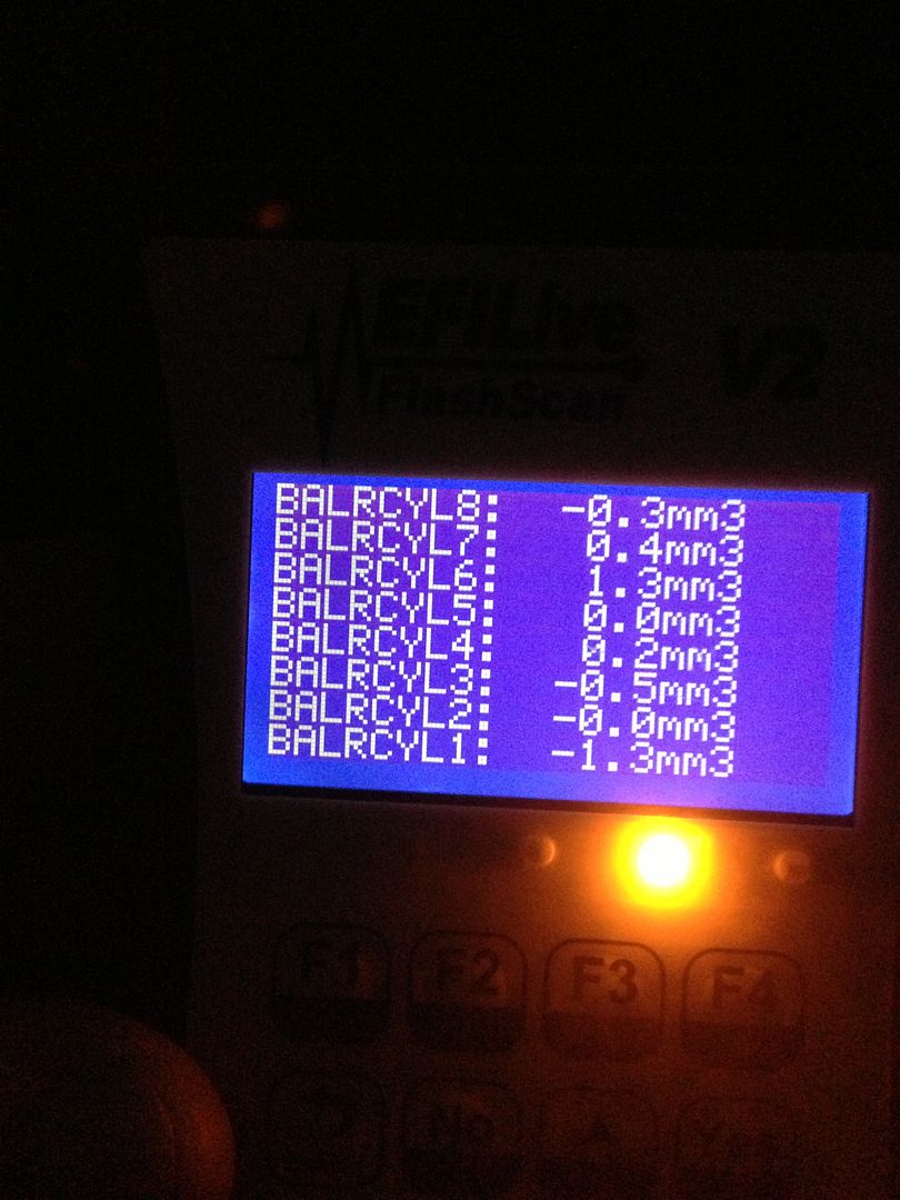
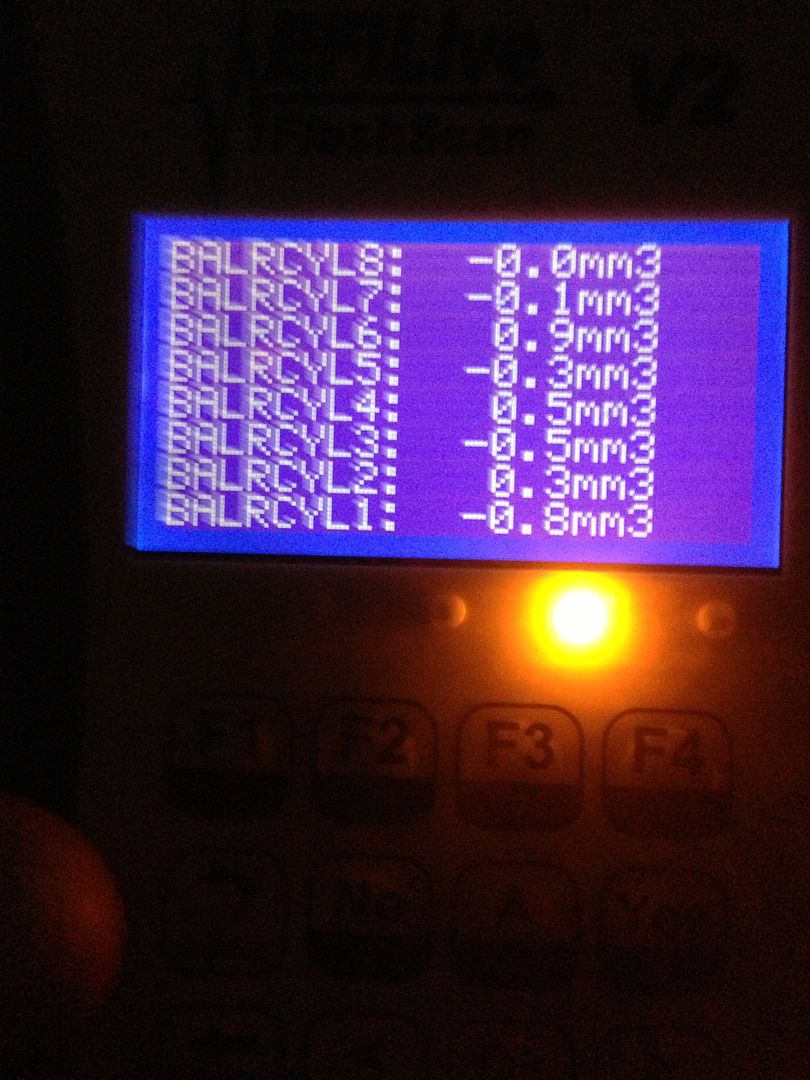
Select quick snapshot (located on the bottom screen of the Tech®2 scan tool) and record the data list seen below for one minute.
Engine RPO- LBZ & LLY: Engine Data 1
Engine RPO- LMM: Fuel System Data
When the snapshot data has been recorded, exit to the Main Menu, then power down and disconnect the Tech 2® from the vehicle. The snapshot should capture the desired fuel rail pressure versus the actual fuel rail pressure.
Important: Make sure you select the correct vehicle snapshot when downloading the information to the TIS Software.
Download the snapshot data to the computer using the TIS Software.
Launch TIS2WEB and enter the main screen. Select Snapshot (Snap) as shown in the graphic above with the arrow.
Click on Start Snapshot (1).
Select the Upload from Handheld button to launch the device selection screen in TIS as shown above.
Select the current snapshot that you just recorded. Then click “OK.” The snapshot data should upload to the computer.
Print the engine data snapshot as shown above. Return a printed copy of this snapshot with the old parts.
Important: Printing a line graph is currently not an available feature in the TIS software. You will have to take a screen print of the graph from TIS and paste the graph into Microsoft® (MS) Paint or Word programs.
Graph and print the desired fuel rail pressure versus the actual fuel rail pressure using TIS software following the directions below:
Click on “Display 6 Graphs” as shown in the graphic above.
Graph Parameters, first select “Actual Fuel Rail Pressure” from the bottom data file this will become the top red line graph value (1).
Select the next green line graph (1) and then click on the “Desired Fuel Rail Pressure” from the bottom data file.
Change the first two Min Y Axis Values (1) from 1.0 to 97.
Change the second two Max Y Axis Values (1) from 65535.0 to 103.
Click OK to display graph.
Copy the graph by pushing down on the Control (Ctrl) and Print Screen (Print Scrn) buttons at the same time on your computer key board.
Open MS Paint and paste the line graph into Paint using the directions below:
Click on “Start” (located in lower left corner of the computer screen) (1).
Select “Programs” (2) or “All Programs.”
Select “Accessories” (3).
Select “Paint” (4) and click on it.
From the top left side toolbar, click on” Edit ' in the Paint screen and select “Paste”. Click on “Paste” and your line graph should appear as shown in the graphic above. If it does not appear you will have to go back to the TIS screen with the line graph and repeat Step 9.7 and Step 9.8.5.
Click on “File” (located in the upper left of the computer screen, under Untitled Paint application).
Select ”Page Setup” and click as shown above.
Under Orientation, click “Landscape”(1).
Under Scaling, click “Fit to” (2).
Under Scaling, enter “1 by 1” pages (3).
Click on OK (4).
Click on “File” (1) (located in the upper left of the computer screen, under Untitled Paint application).
Select “Print” and click. You should have a paper copy of the line graph to send back with the old parts being returned.
Example of Good Fuel Injection Pump Which Shows less than 3 MPa (435 psi) peak-to-peak fluctuation
Note: The graph reading above is an example of a good pump.
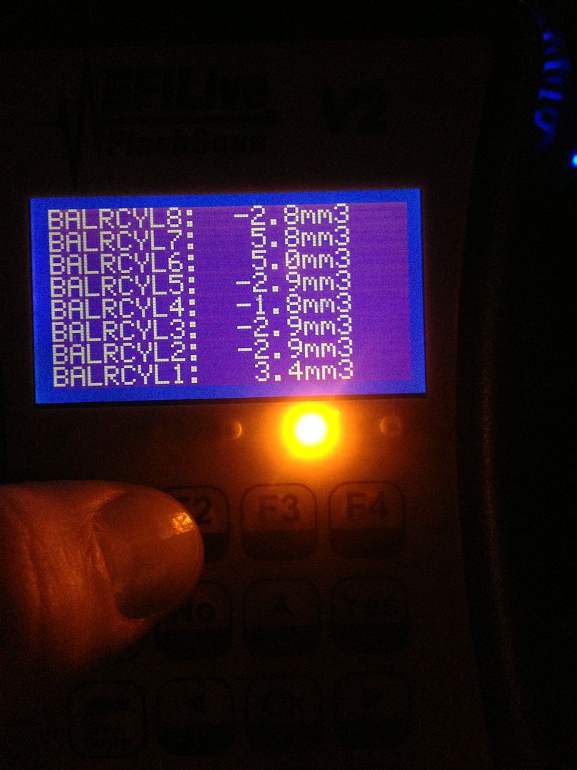
Example of Bad Fuel Injection Pump Which Shows more than 3 MPa (435 psi) peak-to-peak fluctuation
Note: The graph reading above is an example of a bad pump.
Compare your graph to the examples above to determine if the fuel injection pump is good or bad. The straight line is the desired fuel rail pressure (1) and the varying line is your actual fuel line pressure (2).
If less than 3 MPa (435 psi), peak-to-peak pressure fluctuations are observed, refer to normal SI diagnostics.
If more than 3 MPa (435 psi), peak-to-peak pressure fluctuations are observed or there is evidence that the fuel injection pump cup plug is missing, replace the fuel injection pump, both common fuel rails, all eight fuel injectors. and flush the fuel system using Steps 11–19.
Replace the fuel injection pump assembly. Refer to Fuel Injection Pump Replacement in SI.
Replace the left and right fuel injector rails. Refer to Fuel Rail Assembly Replacement in SI.
Replace all eight fuel injectors. Refer to Fuel Injector Replacement in SI.
Reprogram injector flow rates. Refer to Fuel Injector Flow Rate Programming in SI.
Flush all high pressure fuel lines of debris. Refer to Fuel System Cleaning in SI.
Replace the fuel filter. Refer to Fuel Filter Replacement in SI.
Prime the fuel system. Refer to System Priming in SI.
Start the engine and inspect for fuel leaks. Refer to Fuel Leak Diagnosis in SI.
Clear any codes and verify that the condition has been corrected.
Parts Information
Important: Some vehicles may require the removal of the turbo when replacing the fuel injection pump.
Part Number
Description
Qty
97361355
Injector, Fuel (LBZ, LLY ONLY)
8
98002368
Injector, Fuel (LMM ONLY)
8
97361353
Rail, Fuel Injection Fuel-LH
1
97361352
Rail, Fuel Injection Fuel-RH
1
97361351
Pump, Fuel Injection
1
98017645
Filter, Fuel
1
97363723
Seal, Center Intake
(Round)
1
97363570
Gasket, Center Intake
(Rectangle)
2
97223686
Gasket, Engine Coolant Thermostat Housing
(Four bolt hole gasket)
2
94011602
Seal, Thermostat Bypass Pipe
(Upper O-ring)
1
94011603
Seal, Thermostat Bypass Pipe
(Lower O-ring)
1
94011604
Gasket, Water Outlet
(O-ring)
1
94013706
Seal, Oil Level Indicator Tube
1
97365201
Gasket, EGR Outlet Pipe to Intake Tube
1
97367013
Gasket, EGR Valve
(Rectangular)
1
97367014
Gasket, EGR Valve
(Elongate Gasket Located Toward Middle of EGR Valve)
1
97372002
Gasket, EGR Valve Cooler
1
97192618
Gasket, Exhaust Gas Turbo Inlet Pipe
2
97188685
Gasket, Exhaust Manifold Outlet Pipe
2
97373522
Gasket, Turbo Coolant Feed & Return Pipe
2
97208191
Gasket, Turbo Oil Return Pipe (Lower)
1
97331137
Gasket, Turbo Oil Feed Pipe
2
Warranty Information
Important: Make sure you clock in and record the actual repair order clock time when completing this warranty repair. The old fuel injection pump must include a print out of the Engine Data 1 snapshot along with the data line graph showing the desired fuel rail pressures versus the actual fuel rail pressures. If proper documentation is not found with the old parts or you do not show actual repair order clock time, your warranty claim may be denied.
For vehicles repaired under warranty, use:
Labor Operation
Description
Labor Time
J7811*
Diagnose Fuel System Components – Replace
Use Actual Repair Order Clock Time
*This is a unique labor operation for bulletin use only. It will not be published in the Labor Time Guide.
Fuel System Components Check List for Warranty
Warranty Check List
Provide a copy of the vehicles repair order showing actual repair order clock time, vehicles VIN, mileage and customers condition.
Provide a copy of the Engine Data Snapshot.
Provide a copy of the desired fuel rail pressure versus actual fuel rail pressure on a line graph.
Gather all the required information and return it with the fuel injection pump for analysis. If the pump was previously replaced attach the information to the fuel injectors.
* If the fuel injection pump cup plug was missing, the Engine Data 1 snapshot and fuel rail pressure line graph is not required.
This labor operation is on 100% return to the Warranty Parts Center (WPC). DO NOT return any parts associated with J7811 to core. You must return the pump, two rails and injectors when you receive the WPC request. All documentation as outlined above must be returned with the parts. For example: RO with tech notes, snap shot and the graph of the pump.
GM bulletins are intended for use by professional technicians, NOT a "do-it-yourselfer". They are written to inform these technicians of conditions that may occur on some vehicles, or to provide information that could assist in the proper service of a vehicle. Properly trained technicians have the equipment, tools, safety instructions, and know-how to do a job properly and safely. If a condition is described, DO NOT assume that the bulletin applies to your vehicle, or that your vehicle will have that condition. See your GM dealer for information on whether your vehicle may benefit from the information.
WE SUPPORT VOLUNTARY TECHNICIAN CERTIFICATION
© 2013 General Motors. All rights reserved.