Above 2,000 rpm and unable to drive

ripmf666

Active member
Sep 20, 2006
15,123
14
38
47
Wentzville Mo
whats it not starting? my buddy just went thru that dilemma, ended up being a damn mouse ate the coating off of the wires under the underhood fuse panel

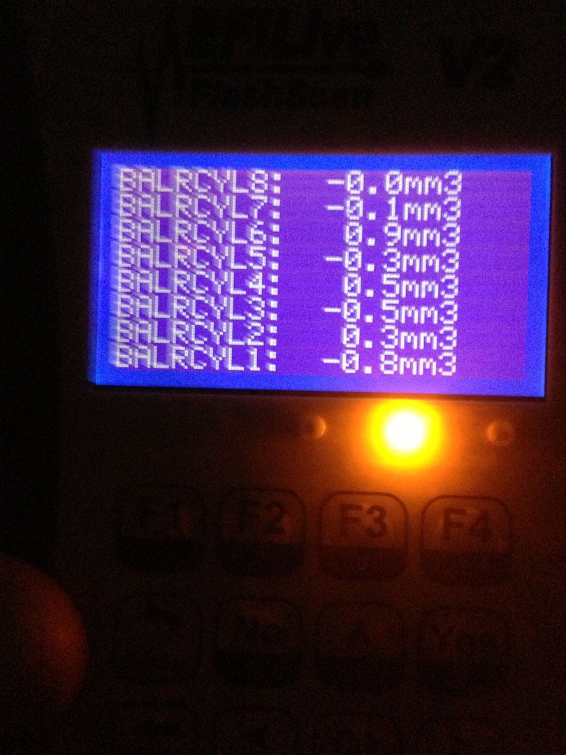
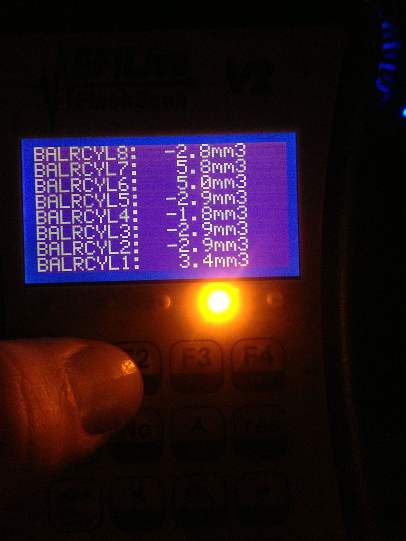
No starts up hell drove to work fine even. Been having a sound that was like a choppy chop chop or flat tire. Only hear it inside truck under dash kinda mid way around cluster but not from on the floor by pedals lol. If you drove by no one could hear this sound I have a video of it I get a thread started tonight after work. But parked truck running fine came out 10hrs later after and remote started I always warm it up no matter it's summer. I have we're balance rates were freaking great before to I was listen to truck as I reved it up did not sound right well it reved up. Then checked rates did not look best then would not rev up good acted like rev limiter. Checked codes P0606 werd Ecm off top of head could be bad also will make truck miss and other shit. Next code well there's the code that it said it would have P0301 cylinder 1 miss fire only codes it had cleared. Drove it easy to house live around corner got to 40 felt chogy the 25 if it went up a hill under power big time no pedal. There is no blow by oil looks good idles fine dis fuel press shows fine actual fuel press shows fine. I even went under and watched balancer no wobble at idle or with some rpm or at start up or shut off. Only time it acts up is when you try to drive or rev up puffs some black smoke and acts like a 2 step and shakes the motor then only. I did pressure was the under the hood few weeks back then after that that werd sound started. I thought I found the sound to be a driver side up pipe leaking at the bellow.
These are stil the stock injectors other then 30% noozles with just shy of 112k I did replace 2 when I built the motor at 30,500 the balance rates the screwed up rates there on one side 1-7
 

ripmf666

Active member
Sep 20, 2006
15,123
14
38
47
Wentzville Mo
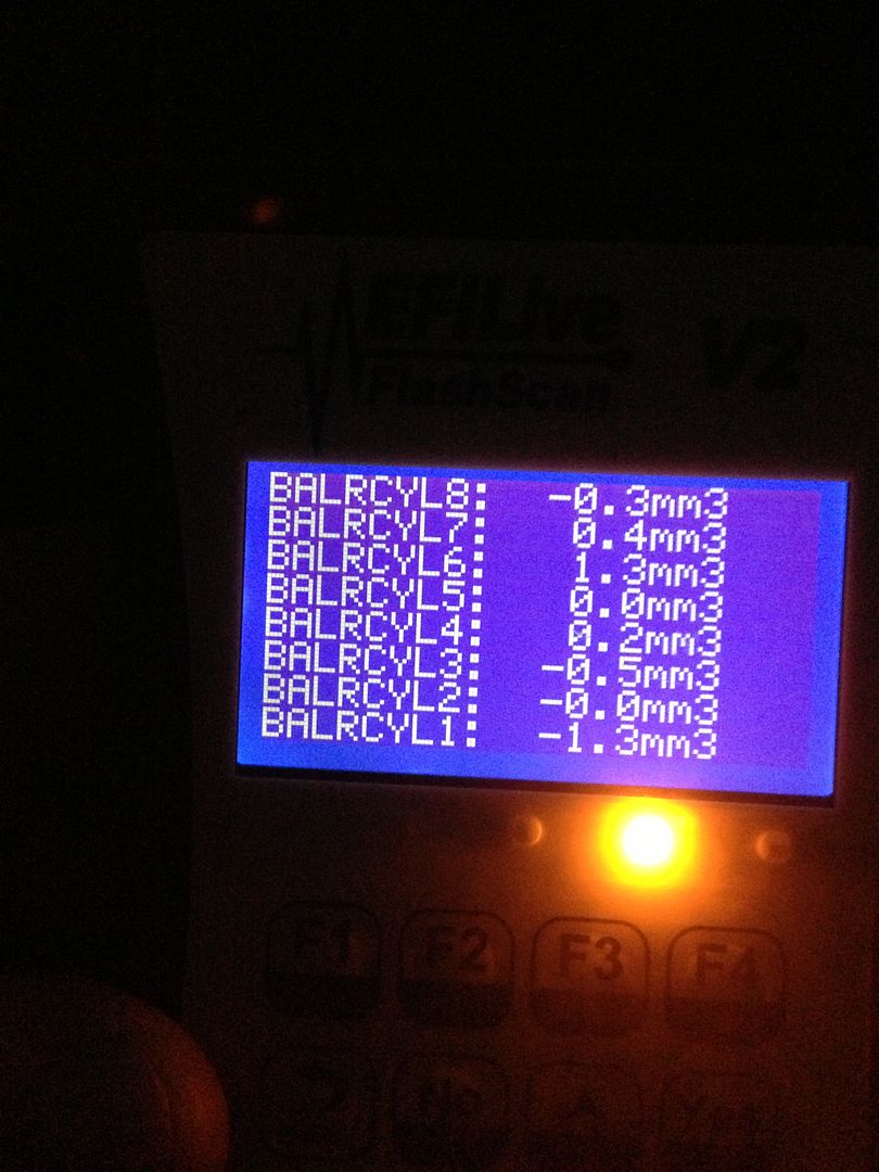
Balance rates from before hand.
null_zpsb1ee9e2d.jpg

null_zpsb579e486.jpg

null_zps30205fb5.jpg

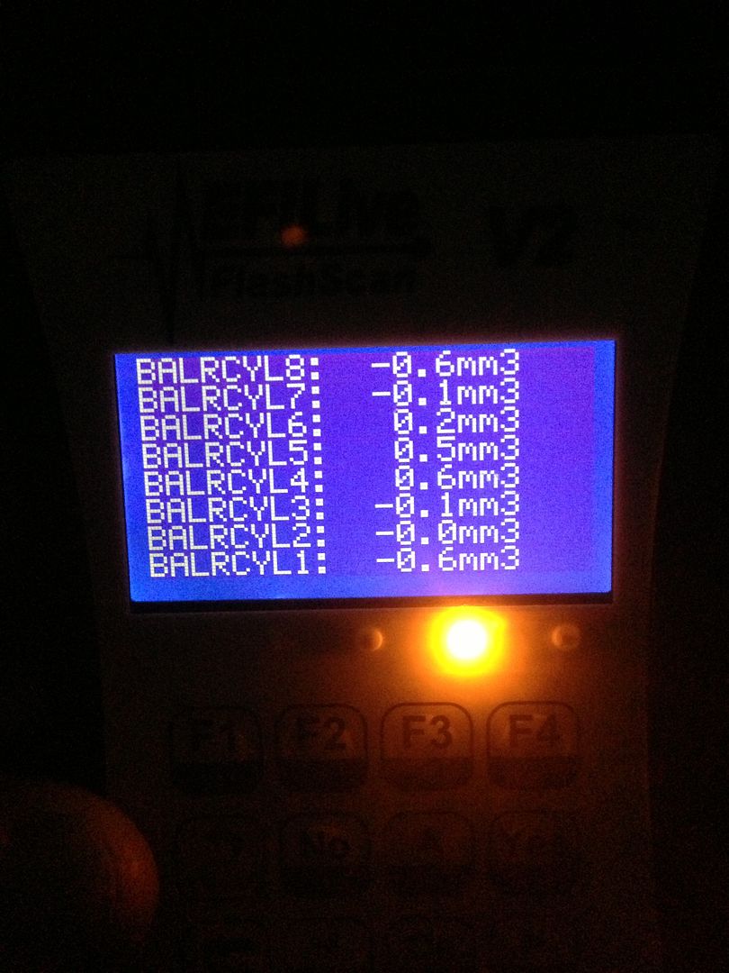
Balance rates now.
null_zpsfda8a4a1.jpg

Video of balance rates.
[YOUTUBE]bOPdlBREBhs[/YOUTUBE]
Walk around after started acting up
[YOUTUBE]UnkOGaI4wEg[/YOUTUBE]
Walk around before acting up
[YOUTUBE]wilp-_0zIUg[/YOUTUBE]
And werd sound that can only be heard from inside while driving
[YOUTUBE]jmUQtUKdMEg[/YOUTUBE]
[YOUTUBE]ROkdlAuu6yg[/YOUTUBE]
 
Last edited:

ripmf666

Active member
Sep 20, 2006
15,123
14
38
47
Wentzville Mo
Off top of my head have not had time to look
It up. Wasn't these controllers known for going bad also ? Could this throw rates off or limit the rpm to act like a 2 step.
null_zpsb0eb28d5.png
 

ripmf666

Active member
Sep 20, 2006
15,123
14
38
47
Wentzville Mo
Don't know what that is Henry but it doesn't sound good.

what are you after in the pic?

The sound I was sure it was a driver side up pipe bellow. There is soot on the firewall and it would be about the right spot.
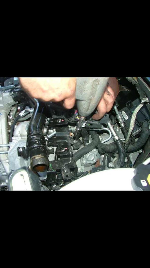
The last pic I posted I had a extra glow plug/injector controller back home. But I have no clue were it would be at this point being that I have been out here. It's the black box with white bar code 2 plugs on top in pic.
 

ripmf666

Active member
Sep 20, 2006
15,123
14
38
47
Wentzville Mo
If you look at this video you will see the leak sure it's that sound I was looking for.
[YOUTUBE]zEbAKMQatYI[/YOUTUBE]
 
Last edited:

ripmf666

Active member
Sep 20, 2006
15,123
14
38
47
Wentzville Mo
Service Information

2006 Chevrolet K Silverado - 4WD | Sierra, Silverado VIN C/K Service Manual | Document ID: 1625300
DTC P0601, P0602, P0603, P0604, P0605, P0606, P0607, P060B, P061C, P062C, P062F, or P2610
Description
These DTCs apply to internal microprocessor integrity conditions within the engine control module (ECM). This diagnostic also addresses if the ECM is not programmed.

The ECM monitors its ability to read and write to the memory. It also monitors a timing function.

DTC Descriptors
This diagnostic procedure supports the following DTCs:

DTC P0602 Control Module Not Programmed
DTC P0606 Control Module Internal Performance
DTC P060B Control Module Analog to Digital Performance
DTC P061C Control Module Engine Speed Performance
DTC P062C Control Module Vehicle Speed Performance
DTC P062F Control Module Long Term Memory Performance
DTC P2610 Control Module Ignition Off Timer Performance
Conditions for Running the DTC
DTC P0602

The following conditions must be met:

The ignition switch is ON.
The controller is identified as a service replacement ECM.
DTC P0606

The following conditions must be met:

The ignition switch is in Run or Crank.
The power take-off (PTO) is inactive.
The cruise control is inactive.
DTC P060B
The engine speed is more than 650 RPM.
The ECM is powered up.
DTC P061C
The ignition is ON.
The engine speed is less than 1,300 RPM.
DTC P062C

The ignition is ON.

DTC P062F

The ignition is ON.

DTC P2610

The ECM is powered up.

Conditions for Setting the DTC
DTC P0602
The ECM has not been programmed at Key On and Engine Off for 0.1 second.
This diagnostic runs continuously.
DTC P0606
The ECM detects a microprocessor undervoltage or overvoltage condition.
OR
The ECM detects an internal bus communication error.
OR
The ECM detects an internal clock error.
OR
The ECM detects an internal injector control error.
All tests run in less than 1 second.
This DTC runs continuously.
DTC P060B
The ECM detects an incorrect internal analog/digital (A/D) signal for less than 1 second.
This DTC runs continuously.
DTC P061C
The ECM detects that there is a difference between the CKP engine speed and the calculated engine speed of more than 320 RPM for less than 1 second.
This diagnostic runs continuously.
DTC P062C
The ECM detects a fault in the ship that calculates redundant vehicle speed for more than 1 second.
This DTC runs continuously.
DTC P062F
The ECM did not complete the last electronic erasable programmable read only memory (EEPROM) write event during the last ECM power down.
This diagnostic runs once per ignition cycle at power up.
DTC P2610
The ignition off-timer is less than 0 second.
OR
The ignition off-timer is less than 5 seconds for more than 10 seconds.
OR
The ignition off-timer is unchanged for 60 seconds.
OR
The ignition off-timer is not incrementing in 1-second intervals.
Action Taken When the DTC Sets
DTC P0602, P0606, P060B, P061C, P062C and P062F
The control module illuminates the malfunction indicator lamp (MIL) when the diagnostic runs and fails.
The control module records the operating conditions at the time the diagnostic fails. The control module stores this information in the Freeze Frame/Failure Records.
DTC P2610
The control module illuminates the MIL on the second consecutive ignition cycle that the diagnostic runs and fails.
The control module records the operating conditions at the time the diagnostic fails. The first time the diagnostic fails, the control module stores this information in the Failure Records. If the diagnostic reports a failure on the second consecutive ignition cycle, the control module records the operating conditions at the time of the failure. The control module writes the operating conditions to the Freeze Frame and updates the Failure Records.
If the diagnostic reports a failure, the control module uses a cold start model based on the engine coolant temperature and intake air temperature at engine start-up. Using the cold start model ensures that the control module is able to determine how much time has elapsed between ignition cycles.
Conditions for Clearing the MIL/DTC
The control module turns OFF the MIL after 3 consecutive ignition cycles that the diagnostic runs and does not fail.
A current DTC, Last Test Failed, clears when the diagnostic runs and passes.
A history DTC clears after 40 consecutive warm-up cycles, if no failures are reported by this or any other emission related diagnostic.
Clear the MIL and the DTC with a scan tool.
Reference Information
DTC Type Reference
Powertrain Diagnostic Trouble Code (DTC) Type Definitions

Circuit/System Testing
Observe the DTCs with the scan tool.
If DTC P0602 or P062F is set, attempt to program the ECM before replacing the ECM. Refer to Service Programming System (SPS).
If DTC P0606 was set while performing SPS Programming, clear the DTCs and exit the diagnostic.
If DTC P0606 was set with DTC P0851 or P0852, first go to Diagnostic Trouble Code (DTC) List - Vehicle.
Test the voltage and ground circuits to the control module for the following:
A short
An open
High resistance
Important: DTC P2610 can be set with a loss of battery voltage to the ECM. Disconnecting the ECM with the ignition ON or an intermittent condition in the Battery Positive Voltage circuit at the underhood fuse block will set DTC P2610.
If DTC P2610 is set, turn the ignition OFF, then completely disconnect the ECM harness connector from the ECM for approximately 1 minute. Reinstall all of the ECM connectors, then clear codes with the scan tool.
If P2610 resets after code clear, test for an intermittent condition in the Battery Positive Voltage circuit at the underhood fuse block connector C2-B8.
Replace the ECM.
Repair Instructions
Important: Always perform the Diagnostic Repair Verification after completing the diagnostic procedure.

Control Module References for ECM replacement, setup, and programming.

© 2013 General Motors. All rights reserved.
 

ripmf666

Active member
Sep 20, 2006
15,123
14
38
47
Wentzville Mo
Service Information

2006 Chevrolet K Silverado - 4WD | Sierra, Silverado VIN C/K Service Manual | Document ID: 1458447
Glow Plug System Description
In the diesel engine, air alone is compressed in the cylinder. Then, after the air has been compressed, a charge of fuel is sprayed into the cylinder and ignition occurs, due to the heat of compression. Eight glow plugs are used as an aid to starting.

Control of the instant start system (ISS) glow plugs is accomplished by a glow control module unit and 4.7 volt glow plugs, requiring 2 seconds to heat up to 1,000°C (1,832°F). The temperature and the power consumption is controlled between the engine control module (ECM) and the controller within a wide range to suit the engine's pre–heating requirements. Each glow plug is energized individually. This capability yields more optimum heat times for the glow plugs, thus pre–glow times can be kept to a minimum for short wait to crank times and maximum glow plug durability. A DTC will set if there is a glow plug system fault.

A normal functioning system operates as follows:

Turn the ignition ON with the engine OFF, and at room temperature.
The glow plugs turn ON and heat up in 2 seconds and then are pulse-width modulated (PWM) for another 2 seconds.
The glow plug wait lamp is ON for 1 second during cold start.
The glow plug wait lamp may not illuminate during a warm engine start.
If the engine is cranked during or after the above sequence, the glow plugs may cycle ON and OFF after the ignition switch is returned from the start position, whether the engine starts or not. The engine does not have to be running to terminate the glow plug cycling.
The glow plug initial ON time will vary based on the system voltage and temperature. Lower temperatures cause longer ON times.

The ECM provides glow plug operation after starting a cold engine. This post-start operation is initiated when the ignition switch is returned to Run, from the Start position. This function helps clean up excessive white smoke and/or poor idle quality after starting.

Glow Plugs
The glow plugs are 4.7 volt heaters in each of the cylinders that turn ON, then pulse-width modulated when the ignition switch is turned to the RUN position prior to starting the engine. They remain pulsing a short time after starting, then they are turned OFF.

A Wait to Start lamp on the instrument panel provides information on engine starting conditions. The Wait to Start lamp will not illuminate during post-start glow plug operation.

Glow Plug/Controller
The glow plug controller is a solid state device which operates the glow plugs. The glow plug controller is connected to the following circuits:

The fuel heater ignition 1 voltage circuit
The battery voltage circuit
The CAN communication circuit located between the engine control module (ECM) and the glow plug controller
The engine ground circuit
The glow plug supply voltage circuits located between the glow plug controller and the glow plugs.
The glow plug diagnostic circuits are directly monitored individually by using a separate transistor to control current to each glow plug. Individual diagnosis is thus possible for every glow plug.

© 2013 General Motors. All rights reserved.
 

ripmf666

Active member
Sep 20, 2006
15,123
14
38
47
Wentzville Mo
Service Information
2006 Chevrolet K Silverado - 4WD | Sierra, Silverado VIN C/K Service Manual | Document ID: 2373697
#PIP4727A: Cleaning Diesel Engine Fuel Injectors - contaminated fire hard idle injection misfire miss SES - (Dec 7, 2009)
Subject: Cleaning Diesel Engine Fuel Injectors

Models: 2001-2010 Chevrolet Express, Kodiak, Silverado
2001-2010 GMC Savana, Sierra, Topkick
Equipped with the 6.6L diesel engines RPO code LB7 LBZ LLY and LMM
This PI was superseded to update model years. Please discard PIP4727.

The following diagnosis might be helpful if the vehicle exhibits the symptom(s) described in this PI.

Condition/Concern:
A dealer may encounter a customer concern of rough running, P0191, or a crank no start.

Poor fuel quality may have induced the rough running, P0191, or no start. A dealer may notice the vehicle has one or more cylinders with the injector balance rates out of specification, a DTC P0191, or a crank no start. When diagnosing a crank no start condition it is possible the injector pintles are stuck closed. A no start with clogged injectors will have sufficient pressure in the fuel rail when the engine is cranked. Cranking pressure will typically be around 4000-5000 psi or 27-34 MPA during a no start due to stuck or clogged injectors.

Recommendation/Instructions:
If a dealer encounters a vehicle with a rough running (high injector balance rate), a P0191, or a no start with sufficient pressure in the fuel rail, cleaning injectors may alleviate the condition.

Injector cleanings are only suggested when the dealer has found fuel contamination or suspects fuel contamination.

Clean injectors if injector balance rates are not within +4 mm³ and -6.9 mm³. Cleaning the injectors may free up a sticking pintle or clean the residue left by poor fuel.
Clean injectors if the engine is a no start, and the vehicle has sufficient pressure in the fuel rail to start. Cranking fuel rail pressure when all 8 injectors are clogged is approximately 4000-5000 psi or 27-34 MPA.
Clean injectors if P0191 has set due to a slow fuel rail pressure (FRP) decay rate. P0191 may set due to an accumulated but harmless varnish build-up on the fuel injectors. If servicing a 2006-2008 model year vehicle please see the newest version of bulletin 09-06-04-022 for P0191 ECM calibration information.
Injector Cleaning Procedure:
To clean the injectors the dealer will be using a mixture of GM Upper Engine Fuel Injector Cleaner p/n 88861802 (88861804 in Canada) and diesel fuel. The cleaner will be connected at the rear of engine fuel line quick disconnects. Use an approved one gallon diesel fuel can for this process. Two fuel lines (also approved for use with diesel fuel) will be needed. Remove the quick disconnects at the rear of the engine. Install the two rubber fuel lines in the place of the fuel suction and return lines. Make sure these hoses are long enough to reach the fuel can sitting safely on the floor next to the vehicle. Use 1/2 gallon of fresh clean number 2 diesel fuel (no bio-diesel) and 13 ounces of GM Upper Engine Fuel Injector Cleaner to complete this process.

Run the engine until the complete mixture has been cycled through the engine.

With a no start condition, try to start the engine multiple times until the mixture starts to flow through the system. Make sure not to overheat the starter during this process. Let the starter cool down between each engagement.

Note: If a heavy concentration of debris or contaminates quickly fills the fuel can (from the return side of the fuel system) do not continue to cycle it through the system. Any contaminated fuel removed from the vehicle will need to be disposed of following city and/or state guidelines.

Evaluate the customer concern after the injector cleaning process has been completed.

Please follow this diagnostic or repair process thoroughly and complete each step. If the condition exhibited is resolved without completing every step, the remaining steps do not need to be performed.

GM bulletins are intended for use by professional technicians, NOT a "do-it-yourselfer". They are written to inform these technicians of conditions that may occur on some vehicles, or to provide information that could assist in the proper service of a vehicle. Properly trained technicians have the equipment, tools, safety instructions, and know-how to do a job properly and safely. If a condition is described, DO NOT assume that the bulletin applies to your vehicle, or that your vehicle will have that condition. See your GM dealer for information on whether your vehicle may benefit from the information.

WE SUPPORT VOLUNTARY TECHNICIAN CERTIFICATION

© 2013 General Motors. All rights reserved.
 

ripmf666

Active member
Sep 20, 2006
15,123
14
38
47
Wentzville Mo
Service Information
2006 Chevrolet K Silverado - 4WD | Sierra, Silverado VIN C/K Service Manual | Document ID: 1852091
#PIP3491C: Highway Speed Excessive Smoke and Fuel Knock - keywords 6.6 additive balance black contamination cylinder injector LBZ LLY lubrication misfire noise pump white - (Aug 1, 2006)
Subject: Highway Speed Excessive Smoke and Fuel Knock

Models: 2004-2006 Chevrolet Express, Kodiak, Silverado
2004-2006 GMC Savana, Sierra, TopKick
Equipped with a 6.6L Duramax Diesel Engine RPO codes LBZ and LLY
This PI was updated to clarify injector copper sealing leaks, and add information about early build injectors. Please discard PIP3491B.

The following diagnosis might be helpful if the vehicle exhibits the symptom(s) described in this PI.

Condition/Concern:
A customer may have a concern of excessive smoke and a fuel knock type noise while driving at highway speed. The customer concern discussed in this PI is more likely to occur in the 15,000 to 20,000 mile range, but may occur at a lower mileage. Excessive smoke may be described as white or black. The smoke associated with this concern will not be a small puff of smoke, but a large plume of smoke that does not dissipate quickly.

Recommendation/Instructions:
Complete current SI diagnostics for any symptoms or DTCs set. Get a large fuel sample from the fuel filter and check for contaminants. If there are signs of contaminants the fuel filter WIF (water in fuel) sensor must be removed. Hard particles will accumulate in the fuel filter WIF sensor area, and close visual inspection of this area will be needed. If contaminants are found, complete the SI procedure for Fuel System Cleaning. Evaluate the customer concern after the fuel system has been cleaned. If no contaminants are found, test drive the vehicle and try to duplicate the customer concern. If the customer concern cannot be duplicated, and the vehicle has only been at the dealer for one time, and one repair attempt, fill the fuel tank and add a fuel conditioner. Only alcohol free water demulsifiers should be used in General Motors diesel engines. The GM Diesel Fuel Conditioner®, The Racor Power Shot Plus®, and the Stanadyne® diesel fuel additives are alcohol free and utilize water demulsifiers to cope with water in the fuel (see service bulletin 03-06-04-017B). Other brands may be available in different areas; be sure that they clearly state that they are alcohol free demulsifiers before use.

If the concern of excessive smoke can be duplicated and the fuel knock is occurring, complete the current SI diagnostics for The Fuel Injector Balance Test with Tech 2.

Monitor and record all cylinder balance rates in drive and neutral.

Injectors that are above +/- 4.0 in park/neutral and +/-6.0 in drive will need to be replaced.

The injector must break both the +/-4.0 and +/-6.0 specification to qualify for replacement.


OR


Cancel the cylinders during the concern.

If canceling the cylinder with the Tech 2 stops the smoke or changes the fuel knock noise, that injector will need to be replaced.

If all the above diagnostics are inconclusive, or the concern is hard to duplicate, follow the steps below:

Remove the injector return lines and inspect the injector return line outlets for signs of rust or corrosion.
If rust or corrosion is found in the injector return line outlets remove the fuel pressure regulator from the fuel injection pump.
Inspect the fuel pressure regulator for corrosion.
If corrosion is found at the injector return outlets and at the pressure regulator, remove the fuel filter from the fuel filter housing and look inside the filter for sediment, rust, or signs of contaminates. Fuel filter inspection includes removing the WIF (water in fuel) sensor and inspecting the filter through the WIF sensor hole.
If rust is found in the injector outlets, the pressure regulator, and the fuel filter, all 8 fuel injectors will need to be replaced. Also replace the fuel filter and pressure regulator during the repair. The injectors will be requested and returned to the WPC and inspected for corrosion. This 8 injector repair is to gather information on fuel system corrosion. If this type of fuel system corrosion is found, the fuel tank must be removed and inspected for contaminants. If contaminants were found in the fuel tank keep a sample of what was found.
If no rust is found in any of the fuel system components and the vehicle is built before 8/20/04, refer to PI # PIP3400A for fuel injector copper sealing washer leaks. A copper seal that leaks (outside of combustion chamber) may be the sign of improper retaining bolt torque, or improper cylinder firing pressures. When a injector copper seal leak is found, there will be combustion soot found outside the combustion chamber (above the copper seal). If the copper seal leak is found the injector should be replaced. Soot found below the copper seal (inside combustion chamber) is not abnormal, and the injector should not be replaced. Be sure to clean injector bores following SI procedures.
Note: If a black smoke/fuel knock has been duplicated on a 2006 model year LLY or LBZ diesel engine, and there is no fuel system contamination/corrosion, check the vehicle build date. If vehicle has less that 4000 miles and was built prior to November 12, 2005 replace all 8 injectors. Complete any injector restriction processes.

Please follow this diagnostic or repair process thoroughly and complete each step. If the condition exhibited is resolved without completing every step, the remaining steps do not need to be performed.

GM bulletins are intended for use by professional technicians, NOT a "do-it-yourselfer". They are written to inform these technicians of conditions that may occur on some vehicles, or to provide information that could assist in the proper service of a vehicle. Properly trained technicians have the equipment, tools, safety instructions, and know-how to do a job properly and safely. If a condition is described, DO NOT assume that the bulletin applies to your vehicle, or that your vehicle will have that condition. See your GM dealer for information on whether your vehicle may benefit from the information.

WE SUPPORT VOLUNTARY TECHNICIAN CERTIFICATION

© 2013 General Motors. All rights reserved.
 

ripmf666

Active member
Sep 20, 2006
15,123
14
38
47
Wentzville Mo
Service Information
2006 Chevrolet K Silverado - 4WD | Sierra, Silverado VIN C/K Service Manual | Document ID: 2390143
#09-06-04-022B: Malfunction Indicator Lamp (MIL) Illuminated, Intermittent DTC P0191, Slow Fuel Rail Pressure (FRP) Decay, Wiring Harness Connections, Voltage Fluctuations/Interruptions (Follow Correction Information - (Jan 28, 2010)
Subject: Malfunction Indicator Lamp (MIL) Illuminated, Intermittent DTC P0191, Slow Fuel Rail Pressure (FRP) Decay, Wiring Harness Connections, Voltage Fluctuations/Interruptions (Follow Correction Information Below)

Models: 2006–2009 Chevrolet Express, Kodiak, Silverado
2006–2009 GMC Savana, Sierra, TopKick
Equipped With Duramax™ Diesel Engine (RPOs LLY, LBZ, LMM)
Please Refer to GMVIS
This bulletin is being revised to update the reprogramming emission controller warranty coverage period information. Please discard Corporate Bulletin Number 09-06-04-022A (Section 06 — Engine/Propulsion System).

Condition
Some customers may comment that the malfunction indicator lamp (MIL) is illuminated, or it illuminates intermittently.

The technician may find DTC P0191 set as current or in history.

Causes
A slow fuel rail pressure (FRP) decay rate may exist, due to an accumulated but harmless varnish buildup on the fuel injectors.
The wiring harness connections may exhibit incorrect crimping, corrosion or poor terminal tension.
Aftermarket electrical equipment may be improperly installed on the vehicle resulting in an interruption or fluctuation in voltage to the engine control module (ECM).
The ECM monitors the FRP sensor voltage signal at engine start up. If the voltage signal is greater than (high fuel rail pressure) a calibrated amount DTC P0191 can set.
The ECM monitors the FRP sensor voltage signal at engine shut down, expecting a decrease to a low voltage signal (low fuel rail pressure) within a calibrated amount of time. If the voltage signal is greater than a specified value within that specific time period, DTC P0191 can set.
Correction
Verify the model year of the vehicle in order to determine which one or both of the following procedures to utilize.

For 2006-2008 Vehicles – Diagnose Possible Slow Fuel Rail Pressure Decay First
Important: DO NOT replace the ECM, the fuel rail pressure regulator, or the fuel rail pressure sensor for this condition.

Start and idle the engine.
Observe the Fuel Rail Pressure Sensor parameter with a scan tool. The parameter should be between 30-40 MPa, depending on engine coolant temperature (ECT).
Turn OFF the engine, and immediately turn the key to the ON position.
Using a stopwatch, observe the decay of the Fuel Rail Pressure Sensor parameter with a scan tool.
The Fuel Rail Pressure Sensor parameter should decay to less than 6.6 MPa within 15 seconds.
If the Fuel Rail Pressure Sensor parameter is more than the specified value within the specified time period, then reprogram the ECM.
Important: If a 2006-2007 LLY, LBZ vehicle has, as one of nine ECM module ID Part Numbers, Part Number 12632483, then reprogramming the ECM will not repair this condition. If a 2007i-2008 LMM vehicle had field action V1819 - 08142 ECM EEPROM - REPROGRAM ECM applied, then reprogramming the ECM will not repair this condition. All 2009 LMM's already have an extended rail pressure bleed down calibration.

A revised software calibration has been released to address this condition. Reprogram the ECM using the Service Programming System (SPS) with the latest calibration available on TIS2WEB. Refer to the SPS procedures in SI.

When using a multiple diagnostic interface (MDI) for reprogramming, ensure that it is updated with the latest software version.

When using a Tech 2® for reprogramming, ensure that it is updated with the latest software version.

During programming, the battery voltage must be maintained within the proper range of 12-15 Volts. Only use the approved Midtronics® PSC 550 Battery Maintainer (SPS Programming Support Tool EL-49642) or equivalent during programming.

For 2006-2009 Vehicles – Use The Following Testing Procedures
Important: DO NOT replace the ECM, the fuel rail pressure regulator, or the fuel rail pressure sensor for this condition.

Wiring Harness Conditions

A secondary cause of DTC P0191 may result from a poor connection at the pigtail connector, or the engine harness connector, incorrect crimps, corrosion, and/or poor terminal tension.

Inspect the six-inch pigtail connector, which connects the FRP sensor to the main engine harness for incorrect crimps, corrosion, and/or poor terminal tension. Refer to Inline Harness Connector End Views for the appropriate model and year, and Circuit Testing and Wiring repairs in SI.
Inspect the Engine Chassis Harness to Engine Harness connector for incorrect crimps, corrosion, and/or poor terminal tension. Refer to Inline Harness Connector End Views for the appropriate model and year, and Circuit Testing and Wiring Repairs in SI.
Voltage Fluctuations/Interruptions at Key Up

Voltage fluctuations at key up, which false trigger a DTC P0191 can be very brief (less than 1 second) and may occur due to any aftermarket equipment installed on the vehicle.

Important: Aftermarket electrical equipment should have a diode connected across the power circuit (coil side) of the relay or solenoid being used in order to prevent transient voltage spikes. For more information on this subject, refer to Corporate Bulletin Number 08-08-45-004A.

Inspect for the proper installation and operation of any aftermarket equipment that may interrupt/interfere with the ignition voltage to the ECM. Refer to Checking Aftermarket Accessories in SI.

The following list is an indication of some of the types of aftermarket equipment that upfitters install.

Theft deterrent systems
Relays or solenoids to operate the electrical system of a snow plow or salt spreader
Handicap ramp safety interlock systems
Internal and external communication and lighting systems
Warranty Information
For vehicles reprogrammed under the 5 year / 100,000 mile (160,000 km) DURAMAX™ Diesel Engine warranty, use:

Labor Operation
Description
Labor Time
J6353
Powertrain Control Module - Engine Reprogramming with SPS
0.4 hr
N6620
Power and Grounds Distribution Wiring and/or Connector Repair or Replacement
Use Published Labor Operation Time
GM bulletins are intended for use by professional technicians, NOT a "do-it-yourselfer". They are written to inform these technicians of conditions that may occur on some vehicles, or to provide information that could assist in the proper service of a vehicle. Properly trained technicians have the equipment, tools, safety instructions, and know-how to do a job properly and safely. If a condition is described, DO NOT assume that the bulletin applies to your vehicle, or that your vehicle will have that condition. See your GM dealer for information on whether your vehicle may benefit from the information.

WE SUPPORT VOLUNTARY TECHNICIAN CERTIFICATION

© 2013 General Motors. All rights reserved.
 

ripmf666

Active member
Sep 20, 2006
15,123
14
38
47
Wentzville Mo
Service Information
2006 Chevrolet K Silverado - 4WD | Sierra, Silverado VIN C/K Service Manual | Document ID: 2312651
#08-06-04-029C: LBZ, LLY, LMM MIL/SES Light On, DTC P0087-Fuel Rail Pressure (FRP) Too Low, Lack of Performance, No Power, Engine Runs Rough, No Start (Diagnose Fuel System Components) - (Jul 20, 2009)
Subject: LBZ, LLY, LMM MIL/SES Light On, DTC P0087– Fuel Rail Pressure (FRP) Too Low, Lack of Performance, No Power, Engine Runs Rough, No Start (Diagnose Fuel System Components)

Models: 2006–2007 Chevrolet Express, Kodiak C4500/C5500 Series, Silverado, Silverado Classic
2006–2007 GMC Savana, Sierra, Sierra Classic, TopKick C4500/C5500 Series
Equipped with 6.6L Duramax ™ Diesel Engine RPOs LBZ, LLY, LMM
Refer to GMVIS
Attention: Please check the vehicle repair order history to determine if a replacement fuel injection pump has already been installed for the above symptoms. If the fuel injection pump has been already replaced, then do not install another new fuel injection pump. The purpose of this bulletin is to aid technicians in the diagnosis and repair of fuel systems components on the Duramax™ Diesel Engine.
This bulletin is being revised to advise technicians that all parts are to be returned to the WPC. Please discard Corporate Bulletin Number 08-06-04-029B (Section 06 — Engine/Propulsion System).

Condition
Some customers may comment on an illumination of the MIL/SES with one or more of the following symptoms:

Lack of Performance
No Power
Engine runs rough
Lack of power
Vehicle may not start
Upon further investigation, the technician may find DTC P0087– Fuel Rail Pressure (FRP) Too Low stored in the ECM.

Cause
A ceramic high pressure valve ball fracture inside the fuel injection pump may lead to internal pump damage resulting in low fuel rail pressure. This condition may contaminate the common fuel rails and fuel injectors with debris. The fuel injection pump may operate, but with reduced output flow.


A high pressure valve fracture may cause the fuel injection pump cup plug (1) to come out, resulting in a no start condition and a possible fluid leak.

Bulletin Diagnostic Tips
There are several bulletin resources available in the Electronic Service Information System (SI) that can provide the technician with information on diagnosis and repair of the fuel system. Some of the bulletins available in SI include:

Information on Diesel Fuel Additives (Bulletin #03-06-04-017)
Information on Injector Bore Cleaning Kit (Bulletin #05-06-04-067)
Information on Servicing Fuel Injectors to Avoid Contamination (Bulletin #03-06-04-036)
Correction
Caution: Remove the fuel tank cap and relieve the fuel system pressure before servicing the fuel system in order to reduce the risk of personal injury. After you relieve the fuel system pressure, a small amount of fuel may be released when servicing the fuel lines, the fuel injection pump, or the connections. In order to reduce the risk of personal injury, cover the fuel system components with a shop towel before disconnection. This will catch any fuel that may leak out. Place the towel in an approved container when the disconnection is complete.

Important: Make sure you clock in and record the actual repair order clock time when completing this repair. A copy of the repair order and a print out of the Engine Data 1 snapshot along with the fuel rail pressure graph may be required. Failure to provide copies of this information may cause your warranty claim to be rejected.

Start by diagnosing the fuel system components by referring to Fuel System Diagnosis in SI.

If the vehicle starts and runs, verify that there are no fuel pump inlet restrictions on the supply side by inspecting for kinked fuel lines or a clogged fuel filter. If the vehicle does not exhibit any fuel supply restrictions or the engine does not start, proceed with the following diagnosis:

If the past repair order history shows the fuel injection pump was replaced, inspect the left fuel rail for debris and/or fuel contamination. It will be necessary to remove the fuel pressure relief valve to visually inspect inside the fuel rail. Refer to Fuel Pressure Relief Valve Replacement in SI.
If particle debris is found in the left fuel rail, perform Steps 12–19.
If no debris is found in the left fuel rail, install the fuel pressure relief valve and tighten. Perform the fuel injector return flow test by referring to Fuel Return System Diagnosis in SI.
Tighten
Tighten the fuel pressure relief valve to 100 Y (74 lb ft).
If the vehicle will not start and/or there is evidence of a leak coming from the fuel injection pump, inspect for a missing or damaged cup plug on the fuel injection pump. If a damaged cup plug is found, perform Steps 11–19.
If the fuel injection pump has not been previously replaced and there is no evidence that the cup plug is damaged, test the fuel injection pump for excessive fuel pressure fluctuations by following Steps 1- 10 below.
Start and idle the engine to normal operating temperatures.
Using a Tech®2 scan tool, build the vehicle information.
Select F2: Special Functions.
Select F2: Fuel Systems.
Select F3: Fuel Pressure Control.
Using the Tech®2 scan tool, increase the fuel rail pressure to 100  MPa (14,503 psi) for desired fuel rail pressure.
Tip: You will have to manually exit the snapshot after 1 minute of recording.
Select quick snapshot (located on the bottom screen of the Tech®2 scan tool) and record the data list seen below for one minute.
Engine RPO- LBZ & LLY: Engine Data 1
Engine RPO- LMM: Fuel System Data
When the snapshot data has been recorded, exit to the Main Menu, then power down and disconnect the Tech 2® from the vehicle. The snapshot should capture the desired fuel rail pressure versus the actual fuel rail pressure.
Important: Make sure you select the correct vehicle snapshot when downloading the information to the TIS Software.
Download the snapshot data to the computer using the TIS Software.

Launch TIS2WEB and enter the main screen. Select Snapshot (Snap) as shown in the graphic above with the arrow.

Click on Start Snapshot (1).

Select the Upload from Handheld button to launch the device selection screen in TIS as shown above.
Select the current snapshot that you just recorded. Then click “OK.” The snapshot data should upload to the computer.

Print the engine data snapshot as shown above. Return a printed copy of this snapshot with the old parts.
Important: Printing a line graph is currently not an available feature in the TIS software. You will have to take a screen print of the graph from TIS and paste the graph into Microsoft® (MS) Paint or Word programs.
Graph and print the desired fuel rail pressure versus the actual fuel rail pressure using TIS software following the directions below:

Click on “Display 6 Graphs” as shown in the graphic above.

Graph Parameters, first select “Actual Fuel Rail Pressure” from the bottom data file this will become the top red line graph value (1).

Select the next green line graph (1) and then click on the “Desired Fuel Rail Pressure” from the bottom data file.

Change the first two Min Y Axis Values (1) from 1.0 to 97.

Change the second two Max Y Axis Values (1) from 65535.0 to 103.
Click OK to display graph.
Copy the graph by pushing down on the Control (Ctrl) and Print Screen (Print Scrn) buttons at the same time on your computer key board.
Open MS Paint and paste the line graph into Paint using the directions below:

Click on “Start” (located in lower left corner of the computer screen) (1).
Select “Programs” (2) or “All Programs.”
Select “Accessories” (3).
Select “Paint” (4) and click on it.

From the top left side toolbar, click on” Edit ' in the Paint screen and select “Paste”. Click on “Paste” and your line graph should appear as shown in the graphic above. If it does not appear you will have to go back to the TIS screen with the line graph and repeat Step 9.7 and Step 9.8.5.
Click on “File” (located in the upper left of the computer screen, under Untitled Paint application).

Select ”Page Setup” and click as shown above.

Under Orientation, click “Landscape”(1).
Under Scaling, click “Fit to” (2).
Under Scaling, enter “1 by 1” pages (3).
Click on OK (4).

Click on “File” (1) (located in the upper left of the computer screen, under Untitled Paint application).
Select “Print” and click. You should have a paper copy of the line graph to send back with the old parts being returned.
Example of Good Fuel Injection Pump Which Shows less than 3 MPa (435 psi) peak-to-peak fluctuation


Note: The graph reading above is an example of a good pump.
Example of Bad Fuel Injection Pump Which Shows more than 3 MPa (435 psi) peak-to-peak fluctuation


Note: The graph reading above is an example of a bad pump.
Compare your graph to the examples above to determine if the fuel injection pump is good or bad. The straight line is the desired fuel rail pressure (1) and the varying line is your actual fuel line pressure (2).
If less than 3 MPa (435 psi), peak-to-peak pressure fluctuations are observed, refer to normal SI diagnostics.
If more than 3 MPa (435 psi), peak-to-peak pressure fluctuations are observed or there is evidence that the fuel injection pump cup plug is missing, replace the fuel injection pump, both common fuel rails, all eight fuel injectors. and flush the fuel system using Steps 11–19.
Replace the fuel injection pump assembly. Refer to Fuel Injection Pump Replacement in SI.
Replace the left and right fuel injector rails. Refer to Fuel Rail Assembly Replacement in SI.
Replace all eight fuel injectors. Refer to Fuel Injector Replacement in SI.
Reprogram injector flow rates. Refer to Fuel Injector Flow Rate Programming in SI.
Flush all high pressure fuel lines of debris. Refer to Fuel System Cleaning in SI.
Replace the fuel filter. Refer to Fuel Filter Replacement in SI.
Prime the fuel system. Refer to System Priming in SI.
Start the engine and inspect for fuel leaks. Refer to Fuel Leak Diagnosis in SI.
Clear any codes and verify that the condition has been corrected.
Parts Information
Important: Some vehicles may require the removal of the turbo when replacing the fuel injection pump.

Part Number
Description
Qty
97361355
Injector, Fuel (LBZ, LLY ONLY)
8
98002368
Injector, Fuel (LMM ONLY)
8
97361353
Rail, Fuel Injection Fuel-LH
1
97361352
Rail, Fuel Injection Fuel-RH
1
97361351
Pump, Fuel Injection
1
98017645
Filter, Fuel
1
97363723
Seal, Center Intake
(Round)
1
97363570
Gasket, Center Intake
(Rectangle)
2
97223686
Gasket, Engine Coolant Thermostat Housing
(Four bolt hole gasket)
2
94011602
Seal, Thermostat Bypass Pipe
(Upper O-ring)
1
94011603
Seal, Thermostat Bypass Pipe
(Lower O-ring)
1
94011604
Gasket, Water Outlet
(O-ring)
1
94013706
Seal, Oil Level Indicator Tube
1
97365201
Gasket, EGR Outlet Pipe to Intake Tube
1
97367013
Gasket, EGR Valve
(Rectangular)
1
97367014
Gasket, EGR Valve
(Elongate Gasket Located Toward Middle of EGR Valve)
1
97372002
Gasket, EGR Valve Cooler
1
97192618
Gasket, Exhaust Gas Turbo Inlet Pipe
2
97188685
Gasket, Exhaust Manifold Outlet Pipe
2
97373522
Gasket, Turbo Coolant Feed & Return Pipe
2
97208191
Gasket, Turbo Oil Return Pipe (Lower)
1
97331137
Gasket, Turbo Oil Feed Pipe
2
Warranty Information
Important: Make sure you clock in and record the actual repair order clock time when completing this warranty repair. The old fuel injection pump must include a print out of the Engine Data 1 snapshot along with the data line graph showing the desired fuel rail pressures versus the actual fuel rail pressures. If proper documentation is not found with the old parts or you do not show actual repair order clock time, your warranty claim may be denied.

For vehicles repaired under warranty, use:

Labor Operation
Description
Labor Time
J7811*
Diagnose Fuel System Components – Replace
Use Actual Repair Order Clock Time
*This is a unique labor operation for bulletin use only. It will not be published in the Labor Time Guide.
Fuel System Components Check List for Warranty
Warranty Check List
Provide a copy of the vehicles repair order showing actual repair order clock time, vehicles VIN, mileage and customers condition.
Provide a copy of the Engine Data Snapshot.
Provide a copy of the desired fuel rail pressure versus actual fuel rail pressure on a line graph.
Gather all the required information and return it with the fuel injection pump for analysis. If the pump was previously replaced attach the information to the fuel injectors.
* If the fuel injection pump cup plug was missing, the Engine Data 1 snapshot and fuel rail pressure line graph is not required.
This labor operation is on 100% return to the Warranty Parts Center (WPC). DO NOT return any parts associated with J7811 to core. You must return the pump, two rails and injectors when you receive the WPC request. All documentation as outlined above must be returned with the parts. For example: RO with tech notes, snap shot and the graph of the pump.

GM bulletins are intended for use by professional technicians, NOT a "do-it-yourselfer". They are written to inform these technicians of conditions that may occur on some vehicles, or to provide information that could assist in the proper service of a vehicle. Properly trained technicians have the equipment, tools, safety instructions, and know-how to do a job properly and safely. If a condition is described, DO NOT assume that the bulletin applies to your vehicle, or that your vehicle will have that condition. See your GM dealer for information on whether your vehicle may benefit from the information.

WE SUPPORT VOLUNTARY TECHNICIAN CERTIFICATION

© 2013 General Motors. All rights reserved.
 

ripmf666

Active member
Sep 20, 2006
15,123
14
38
47
Wentzville Mo
Service Information

2006 Chevrolet K Silverado - 4WD | Sierra, Silverado VIN C/K Service Manual | Document ID: 1640796
Fuel Injector Balance Test with Tech 2 (Automatic Transmission)
Diagnostic Instructions
Perform the Diagnostic System Check - Vehicle prior to using this diagnostic procedure.
Review Strategy Based Diagnosis for an overview of the diagnostic approach.
Diagnostic Procedure Instructions provides an overview of each diagnostic category.
Circuit/System Description
The fuel injector balance test is performed when a misfire, knock, excessive smoke, or rough running condition exists with no electrical DTCs. This test uses the Balance Rate and Cylinder Power Balance test to identify cylinders that are not producing the designed power output. The balance rate adjustments are utilized by the engine control module (ECM) only at idle. The balance rates are the fuel adjustments for each individual cylinder based on the variations in engine crankshaft speed. The balance rates will change depending on if the transmission is in Neutral or Drive. During the Cylinder Power Balance portion of the test, the ECM turns OFF individual injectors while the engine is running. The ECM adjusts for the drop in engine RPM during cancellation and may not change on the scan tool display. The lack of power at the cancelled cylinder will feel like a misfiring cylinder or vibration. If a fuel injector is turned OFF and there is a no difference felt when compared to the other cylinders, that cylinder is identified with the concern. If the customer concern occurs during idle or during off-idle tip in acceleration, the balance rates are used to identify the cylinder with a fault related to the fuel injector or engine compression.

Diagnostic Aids
The Cylinder Power Balance Test may be performed at any engine speed or load from idle to wide open throttle (WOT). There is a 5-minute time limit for each test.
A high balance rate may be caused by a fuel injector or compression only if the ECM can control fuel pressure.
Circuit/System Verification
Important: If any DTCs other than DTC P0300–P0308 are set, refer to Diagnostic Trouble Code (DTC) List - Vehicle.

Start and run the engine until the coolant temperature is more than 82°C (180°F). Turn OFF all accessories.
Perform the fuel pressure regulator test, refer to Fuel Pressure Regulator Diagnosis.
Apply the parking brake and hold the brake pedal in the fully applied position. A hissing noise will be noticeable when the brake pedal is fully applied. Place the transmission in Drive and idle the engine for a minimum of 30 seconds. With a scan tool, observe the balancing rates parameters for cylinders 1–8 while the engine is at idle speed. Repeat this procedure with the transmission in the Park or Neutral position. Balance Rates should be between +4 mm³ and −4mm³ in Park or Neutral and +6mm³ and −6mm³ in Drive.
Important:
The Cylinder Power Balance Test must be performed under the conditions for which the customer concern occurred.
Do not operate the cruise control during this test. Cruise control may cause a brief surge of engine speed after the completion of the test.
Perform the Cylinder Power Balance Test with a scan tool. During cylinder cancellation a noticeable power difference will feel like a misfiring cylinder or vibration.
Circuit/System Testing
Important:

You must perform the Circuit/System Verification before proceeding with Circuit/System Testing.
If any fuel spray comes out of a glow plug hole during the compression test, replace the fuel injector of the affected cylinder.
Perform the engine compression test. Refer to Engine Compression Test.

If the compression indicated any of the cylinders had low compression, refer to Symptoms - Engine Mechanical.
Important:
Failure to correctly identify the cylinder positions may result in the replacement of the wrong injector.
During replacement of the injectors, inspect the inlet and outlet fittings for corrosion or contamination. Refer to Contaminants-in-Fuel Diagnosis.
If the engine did not have low compression on any of the cylinders, replace the fuel injectors on the cylinders that had low cylinder power contribution, high balance rates, or a noise/smoke change during cancellation.
Repair Instructions
Perform the Diagnostic Repair Verification after completing the diagnostic procedure.

Fuel Pressure Regulator Replacement
Fuel Injector Replacement
© 2013 General Motors. All rights reserved.