NSBU help

Jsle131

New member
Jan 17, 2022
23
1
3
My truck threw a U-joint and cracked the bell housing and rear engine cover. Put it back together and replaced NSBU and the Connectors (bought from Rockauto). Truck will not crank in P or N. If I unplug the 7 pin Connector and use a Jumper wire across pins E&G the truck will run but the transmission will not engage in any gear. I have continuity between pins E&G and A&D on the NSBU in P.


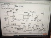
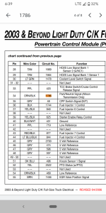
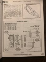
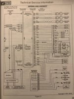
I have the 7 pin Connector wired as follows.
A- Orange and black.
B. Lt green.
C. Pink.
D. Black and white.
E. Pink.
F. Yellow.
G. Drk Green.

4 pin connector.
A. Blk/white
B. Grey.
C. White.
D. Yellow.

Batteries both have 12 volts and are hooked up to a Maintainer.

I have 34 transmission codes that will not clear.

I reinstalled the original black switch and still have the same issue.

Is it possible I have the 4 pin connector wired wrong or a bad NSBU? Is their any way to test the NSBU switch with a multimeter?
 

Jsle131

New member
Jan 17, 2022
23
1
3
Anyone have any ideas? I have 12v at both pink wires going to the NSBU switch with the key on but no power coming from dark green when the key is turned to start (tested at the NSBU switch). Picked up another NSBU from the Allison dealer and still having the same issue.
 

Attachments

  • PXL_20220124_162119340.MP.jpg
    PXL_20220124_162119340.MP.jpg
    369.5 KB · Views: 22

2004LB7

Well-known member
Dec 15, 2010
6,386
1,750
113
Norcal
what does the dash gear selector show? what position did you have the selector in when you put the NSBU switch in?
 

Jsle131

New member
Jan 17, 2022
23
1
3
Dash selector shows it's in the correct positions. NSBU was installed in Neutral. Orange and black wire at NSBU only has 10vs?
 

Attachments

  • Screenshot_20220125-183921.png
    Screenshot_20220125-183921.png
    497.6 KB · Views: 18

Ron Nielson

Active member
Oct 11, 2009
691
116
43
Berryton, KS
The ground (zone 4)for the NSBU (and other important components like ECM) is at the right rear corner of the block. You may have disrupted that when replacing your cracked bell housing. Double check that ground to make sure ground will hold a load, say at least 1 amp or so. Don't test with a volt meter, use a light bulb, power probe or other load.

Also check voltage of the or/blk wire at the ECM connector (to battery ground) see the voltage there
 

Attachments

  • 2003 Ground Zones.pdf
    57.1 KB · Views: 5
  • 2003 PRNDL NSBU.pdf
    45 KB · Views: 6
  • Like
Reactions: Leadfoot

Jsle131

New member
Jan 17, 2022
23
1
3
Visually inspected the grounds in Zone 4, everything looks good. Working on either getting a power probe or building a load tester out of a light bulb.

Back probed pin 34 on ECM ( orange and black wire) only getting 10v.
 

dndj

Boost!
Apr 13, 2019
302
33
28
Oregon
Reviewing the pin functions, with help from the ATSG manual and the GM upfitter manuals. I attached the diagrams. NSBU has 2 connectors - C2 (7 pins) and C1 (4 pins).

C1 - A is range switch A
C1 - B is range switch C
C1 - C is range switch P
C1 - D is range switch B

C2-A P/N switch routed to ECM J1-34. Unfortunately, not described in ATSG manual, but I believe this should be GND in P and N (Upfitter manual)
C2-B switch connected to C2-C, switch closes in P and provides 12v to BTSI fuse -> brake switch -> A/T shift lock solenoid in steering column.
C2-C 12v power from B/U fuse, hot in RUN and START
C2-D Ground
C2-E 12v power from IGN E fuse, hot in RUN and START
C2-F switch connected to C2-C, switch closes in R connecting power to the BCM, which in turns on the reverse lamps
C2-G switch connected to C2-E, switch closes in P or N, supplying power to the start relay coil. ECM grounds the other side of the relay coil when cranking.

I don't believe you should be seeing 10v on ECM pin J1-34. That should be ground or +12v. Check for continuity between the NSBU end (C2-A) of the black/orange wire and the ECM end at J1-34.
 

Attachments

  • 4.jpg
    4.jpg
    276.8 KB · Views: 16
  • 5.jpg
    5.jpg
    298 KB · Views: 15

Jsle131

New member
Jan 17, 2022
23
1
3
Reviewing the pin functions, with help from the ATSG manual and the GM upfitter manuals. I attached the diagrams. NSBU has 2 connectors - C2 (7 pins) and C1 (4 pins).

C1 - A is range switch A
C1 - B is range switch C
C1 - C is range switch P
C1 - D is range switch B

C2-A P/N switch routed to ECM J1-34. Unfortunately, not described in ATSG manual, but I believe this should be GND in P and N (Upfitter manual)
C2-B switch connected to C2-C, switch closes in P and provides 12v to BTSI fuse -> brake switch -> A/T shift lock solenoid in steering column.
C2-C 12v power from B/U fuse, hot in RUN and START
C2-D Ground
C2-E 12v power from IGN E fuse, hot in RUN and START
C2-F switch connected to C2-C, switch closes in R connecting power to the BCM, which in turns on the reverse lamps
C2-G switch connected to C2-E, switch closes in P or N, supplying power to the start relay coil. ECM grounds the other side of the relay coil when cranking.

I don't believe you should be seeing 10v on ECM pin J1-34. That should be ground or +12v. Check for continuity between the NSBU end (C2-A) of the black/orange wire and the ECM end at J1-34.
Their is continuity between J1 pin 34 and Pin A on the NSBU switch.
 

Ron Nielson

Active member
Oct 11, 2009
691
116
43
Berryton, KS
Visually inspected the grounds in Zone 4, everything looks good. Working on either getting a power probe or building a load tester out of a light bulb.

Back probed pin 34 on ECM ( orange and black wire) only getting 10v.
I hope you disconnected the non-ecm connector for this cable, such that the only path to ground would be to the battery negative terminal. Also, looking at a connection is not the same as testing the connection. Sometimes the results are the same, sometimes not.
 

Jsle131

New member
Jan 17, 2022
23
1
3
I hope you disconnected the non-ecm connector for this cable, such that the only path to ground would be to the battery negative terminal. Also, looking at a connection is not the same as testing the connection. Sometimes the results are the same, sometimes not.
Unplugged the NSBU and hooked multimeter to negative side of the battery then probed through the ECM connector at pin 34, does that sound right?
 

2004LB7

Well-known member
Dec 15, 2010
6,386
1,750
113
Norcal
have you checked the starter relay in the fuse box? if you jump the 30 & 87 pins will the engine crank? also, with the shifter in park or neutral there should be voltage on pin 85 or 86 and the other pin without voltage is the pin the ECM grounds out via C2-4 to turn on the relay. the power comes from the fuse box, goes down to the park/neutral switch then up the starter relay in the fuse box
 

dndj

Boost!
Apr 13, 2019
302
33
28
Oregon
Unplugged the NSBU and hooked multimeter to negative side of the battery then probed through the ECM connector at pin 34, does that sound right?
No. ECM J1-34 is not a ground, this is a P/N signal from the NSBU to the ECM. Ron is advising verifying your ground connectivity. One possible test is to verify (with both C1 and C2 unplugged from NSBU) that C2-D is a solid connection to battery ground.
 
Last edited:

Jsle131

New member
Jan 17, 2022
23
1
3
Okay, so ground C2-D directly to the battery and then measure voltage at J1-34?
 

dndj

Boost!
Apr 13, 2019
302
33
28
Oregon
Okay, so ground C2-D directly to the battery and then measure voltage at J1-34?

Don't worry about J1-34 for now. Just verify solid grounding of the NSBU to the battery terminal. Ideally with a load, not just with a digital voltmeter/continuity check.
 
  • Like
Reactions: Jsle131

dndj

Boost!
Apr 13, 2019
302
33
28
Oregon
After the ground check, from reading your description, another thing that you said in post #2 is a huge clue.

When the truck is in P, +12v from C2-E should pass through to C2-G. If you aren't seeing power at C2-G when the truck is in RUN or START position, (and there is power at C2-E, which you've said previously) then something is mechanically wrong. The NSBU should be shorting C2-E to C2-G when in park. This enables power to the start relay.
 

Jsle131

New member
Jan 17, 2022
23
1
3
After the ground check, from reading your description, another thing that you said in post #2 is a huge clue.

When the truck is in P, +12v from C2-E should pass through to C2-G. If you aren't seeing power at C2-G when the truck is in RUN or START position, (and there is power at C2-E, which you've said previously) then something is mechanically wrong. The NSBU should be shorting C2-E to C2-G when in park. This enables power to the start relay.
Mechanical wrong with the transmission or the NSBU switch itself? When I do the load test I'm connecting the light bulb to the ground at C2-D and a power supply correct?
 

dndj

Boost!
Apr 13, 2019
302
33
28
Oregon
Mechanical wrong with the transmission or the NSBU switch itself? When I do the load test I'm connecting the light bulb to the ground at C2-D and a power supply correct?

Yes - bulb to +12v on the battery, ground on C2-D of the harness while both C2 and C1 remain unplugged from NSBU.

Mechanically, I mean the NSBU is not rotating to the correct position when in Park somehow, when it should be shorting out C2-E and C2-G when in park. Easy to verify - unplug C1 and C2 and check continuity between these two. I believe new NSBUs come with a bracket to ensure the rotation is set to the neutral position (as should the trans also be), which is supposed to remain in place until installed to keep everything in sync. Perhaps something is not clocked correctly.
 
Last edited:

Jsle131

New member
Jan 17, 2022
23
1
3
Yes - bulb to +12v on the battery, ground on C2-D of the harness while both C2 and C1 remain unplugged from NSBU.

Mechanically, I mean the NSBU is not rotating to the correct position when in Park somehow, when it should be shorting out C2-E and C2-G when in park. Easy to verify - unplug C1 and C2 and check continuity between these two. I believe new NSBUs come with a bracket to ensure the rotation is set to the neutral position (as should the trans), which is supposed to remain in place until installed to keep everything in sync. Perhaps something is not clocked correctly.
Yes the new switch has a little metal bracket that holds it in the neutral position. I will double-check the position of the switch, it was installed in N. I hooked a light bulb(9006 headlight) up to the C2-D ground and the battery and the light bulb was nice and bright.
 

Jsle131

New member
Jan 17, 2022
23
1
3
have you checked the starter relay in the fuse box? if you jump the 30 & 87 pins will the engine crank? also, with the shifter in park or neutral there should be voltage on pin 85 or 86 and the other pin without voltage is the pin the ECM grounds out via C2-4 to turn on the relay. the power comes from the fuse box, goes down to the park/neutral switch then up the starter relay in the fuse box
Relay is good, truck will crank when you jump 30&87. It seems that it is not sending power back up to the relay from the NSBU.
 

dndj

Boost!
Apr 13, 2019
302
33
28
Oregon
Next recommendation: put the truck in neutral. Pull the NSBU connectors C1, C2 off. Probe on the NSBU pins and verify C2-E and C2-G are shorted together (they should be connected in P and in N).