☆edit: PROBLEM SOLVED, READ LAST POST☆
Hey yall. New to the forums but could use some help with a duramax glow plug issue.
I dont see a help forum page, not sure where this goes..
2003 GMC sierra duramax
6.6 auto
California Emissions
Working on a customer vehicle. Its having a glow plug issue with a P0380 code. I've read though hours of googling p0380 and duramax gp issues.
1.) I cant seem to get the plugs to cycle on or 12 volts anywhere when the gp light comes on the dash. They should receive 11-12v at gp connector when key-on cycled correct?
2.) The input voltage to the gp is different than the feedback voltage correct?
11v-12v to glowplugs?
Feedback 5-6volts?
3.) My reader wont let me view the live feedback data or manually cycle the gp to check for voltage.
Which wire can I probe to read the feedback voltage to ecu?
Found on a fourm:
(Conditions for Setting the DTC)
•The glow plugs are commanded OFF and the glow plug feedback is more than 2 volts
or
•The glow plugs are commanded on and the glow plug feedback is not between 5 volts and 6.2 volts.
Here's a basic list of what I've found after taking some readings:
•The CEL when cleared throws an immediate p0380 pending code after cleared, Then will comeback after a few key cycles.
•All glowplugs look fairly new (possibly replaced by previous owner trying to solve issue?
• They are correct 11V for the lb7 not the lly 4.7v
•They all ohmed @1.0ohms
•All individual Wires to each GP (CA emmisions w/ individual wires NOT bus bar connections)
@ 0.6 ohms disconnected from GP
@ 1.8 ohms connected to GP (grounded)
•When leads connected and tested with a Testlight all GP'S show proper ground.
•When pinned from the GP controller side harness (4 wire plug ) each bank shows correct ground.
•Middle plug port on GP controller
(Not the harness. The controller itself with just 12v to terminal. No plugs connected)
Pins on controller from Left to Right and color wire it would go to:
0v - pink
12v - blue
12v - yellow/pink stripe
12v - yellow
This is two tests with the OLD controller and a NEW one. The new controller did NOT solve the issue.
☆both controllers show the same middle port voltage listed above (P,B,Y,Y)
OLD GP controller:
☆ (The two outter 4 pin plug ports that feed direct to glowplug wires)
•4 Outter pins: 0 volts on all 8 pins
This stays the same with the middle harness plugged in or disconnected.
NEW GP controller:
☆(The two outter 4 pin plug ports that feed direct to glowplug wires)
•4 Outter pins: 9v on all 8 pins (with NO middle harness plug in)
•When the middle harness plugged in (pink,blue,yellow/p, yellow) voltage drops to and stays at 2.5volts
•When the outter plugs to the GP controller are connected, I read NO voltage to the back side of the harness or to the GP wire connector.
• Middle port of thenGlowplug controller: HARNESS SIDE// UN-plugged.
(The middle harness going back to main harness/ecu)
•Multimeter showed ground
•Testlight showed:
Pink - Strong ground (bright light)
Blue - weak ground (dim light)
Yellow/pink stripe- no ground (no light)
Yellow -weak ground (dim light)
On the intake heater i have :
•12v to the hot side of the relay (direct from the glowplug controller 12v terminal so makes sense)
•12v to the small wires going to the relay
• 0 volts to the Other terminal output (side that feeds the intake heater wire)
•intake heater side terminal from relay shows ground when key-off.
☆ Last owner had a 5v ignition wire jumper going to it.
Its alot of info, I hope I wrote it all easily and able to understand. Any help would be greatly appreciated. I think I just read to many posts and got myself stuck in a testing loop.
I'm not sure if the glowplugs aren't coming on at all and that's throwing the code
Or
If the feedback voltage or a problem is commanding them to stay off and that's throwing the code.
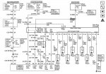
A wiring diagram or if someone can tell me there the 4 signal wires go (pink,blue,yellow, yellow) would be very helpful.
Thanks for any input
Hey yall. New to the forums but could use some help with a duramax glow plug issue.
I dont see a help forum page, not sure where this goes..
2003 GMC sierra duramax
6.6 auto
California Emissions
Working on a customer vehicle. Its having a glow plug issue with a P0380 code. I've read though hours of googling p0380 and duramax gp issues.
1.) I cant seem to get the plugs to cycle on or 12 volts anywhere when the gp light comes on the dash. They should receive 11-12v at gp connector when key-on cycled correct?
2.) The input voltage to the gp is different than the feedback voltage correct?
11v-12v to glowplugs?
Feedback 5-6volts?
3.) My reader wont let me view the live feedback data or manually cycle the gp to check for voltage.
Which wire can I probe to read the feedback voltage to ecu?
Found on a fourm:
(Conditions for Setting the DTC)
•The glow plugs are commanded OFF and the glow plug feedback is more than 2 volts
or
•The glow plugs are commanded on and the glow plug feedback is not between 5 volts and 6.2 volts.
Here's a basic list of what I've found after taking some readings:
•The CEL when cleared throws an immediate p0380 pending code after cleared, Then will comeback after a few key cycles.
•All glowplugs look fairly new (possibly replaced by previous owner trying to solve issue?
• They are correct 11V for the lb7 not the lly 4.7v
•They all ohmed @1.0ohms
•All individual Wires to each GP (CA emmisions w/ individual wires NOT bus bar connections)
@ 0.6 ohms disconnected from GP
@ 1.8 ohms connected to GP (grounded)
•When leads connected and tested with a Testlight all GP'S show proper ground.
•When pinned from the GP controller side harness (4 wire plug ) each bank shows correct ground.
•Middle plug port on GP controller
(Not the harness. The controller itself with just 12v to terminal. No plugs connected)
Pins on controller from Left to Right and color wire it would go to:
0v - pink
12v - blue
12v - yellow/pink stripe
12v - yellow
This is two tests with the OLD controller and a NEW one. The new controller did NOT solve the issue.
☆both controllers show the same middle port voltage listed above (P,B,Y,Y)
OLD GP controller:
☆ (The two outter 4 pin plug ports that feed direct to glowplug wires)
•4 Outter pins: 0 volts on all 8 pins
This stays the same with the middle harness plugged in or disconnected.
NEW GP controller:
☆(The two outter 4 pin plug ports that feed direct to glowplug wires)
•4 Outter pins: 9v on all 8 pins (with NO middle harness plug in)
•When the middle harness plugged in (pink,blue,yellow/p, yellow) voltage drops to and stays at 2.5volts
•When the outter plugs to the GP controller are connected, I read NO voltage to the back side of the harness or to the GP wire connector.
• Middle port of thenGlowplug controller: HARNESS SIDE// UN-plugged.
(The middle harness going back to main harness/ecu)
•Multimeter showed ground
•Testlight showed:
Pink - Strong ground (bright light)
Blue - weak ground (dim light)
Yellow/pink stripe- no ground (no light)
Yellow -weak ground (dim light)
On the intake heater i have :
•12v to the hot side of the relay (direct from the glowplug controller 12v terminal so makes sense)
•12v to the small wires going to the relay
• 0 volts to the Other terminal output (side that feeds the intake heater wire)
•intake heater side terminal from relay shows ground when key-off.
☆ Last owner had a 5v ignition wire jumper going to it.
Its alot of info, I hope I wrote it all easily and able to understand. Any help would be greatly appreciated. I think I just read to many posts and got myself stuck in a testing loop.
I'm not sure if the glowplugs aren't coming on at all and that's throwing the code
Or
If the feedback voltage or a problem is commanding them to stay off and that's throwing the code.
A wiring diagram or if someone can tell me there the 4 signal wires go (pink,blue,yellow, yellow) would be very helpful.
Thanks for any input
Last edited: