Info: Duramax Valve Lash Tutorial.

McRat

Diesel Hotrodder
Aug 2, 2006
11,249
26
38
64
Norco CA
www.mcratracing.com
First a little background information -

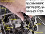
A four-stroke engine, like our Duramax, has intake valve(s) and exhaust valve(s). In our case, we have 2 intake valves and 2 exhaust valves for each cylinder. These valves are open roughly 200 degrees of crankshaft revolution. Since a four-stroke engine requires 2 full crankshaft revolutions to complete a power cycle (360° x 2 = 720°), the valves are open less than one-third of the time. When the valve is open, the lifter is riding on the camshaft lob and the pushrod and rocker arm is holding the valve open. But when setting the valve lash or clearance, we are concerned about what the valve is doing when it's closed, and the cam is on it's base circle with no lift. With solid lifter engines, you must have some "play" in the lifter/pushrod/rocker-arm assembly or the valve won't shut completely, and you will have low compression, poor performance, and you'll burn the valves. If you have too much "play", you will have poor performance, excessive noise and perhaps shorten the life of the valvetrain components. We call this play "lash" or "clearance". For our engine, the recommended number is 0.012", aka twelve thousandths. This allows for heat expansion and valve face/seat wear. Most engines will get tighter (less lash) over time in my experience. You can make a little more high RPM power by running towards the tight side.

Your Duramax engine is 32 valve V8 with 16 pushrods that rides on a solid lifter roller cam. Normally the valves will never require adjustment during it's service life. But for us hotrodders, you will need to do this if you:

Swap heads
Swap pushrods
Swap headgaskets
or anything else that might change the valve adjustment.

You should not have to do this if you just change to head studs, but you might as well check them when you are there.

I imagine GM has a great procedure for these, but I haven't bought the service manual. So this is the way I adjust valves on bikes, cars, trucks, boats, lawnmowers, or anything else I've tampered with.

You will need:

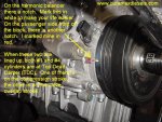
36mm 12-pt socket and breaker bar/ratchet
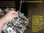
14mm wrench (I like using a long handle version)
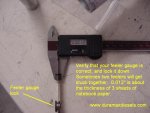
A set of feeler gauges that includes a single 0.012" blade, or whatever value you are setting them to.

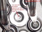
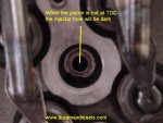
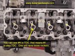
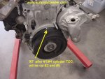
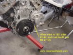
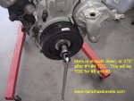
OK, I do engines at TDC (Top Dead Center) compression-stroke only. There are 2 TDC's for each cylinder, TDC Compression, and TDC Overlap. Both valves are closed on Compression, and both are open slightly on Overlap.

I'm going to do them by the firing order as well, to insure I do not skip a cylinder. My way takes a couple minutes longer, but IMO is less troublesome.

Our firing order is 12784563:
 

Attachments

  • _valveFiringOrder.JPG
    _valveFiringOrder.JPG
    67.2 KB · Views: 1,104

McRat

Diesel Hotrodder
Aug 2, 2006
11,249
26
38
64
Norco CA
www.mcratracing.com
I'm going to start with Cylinder #1, which is the passenger side front. So I'm going to line up the timing marks on the harmonic balancer:
 

Attachments

  • _valve0deg.JPG
    _valve0deg.JPG
    80.7 KB · Views: 1,035

McRat

Diesel Hotrodder
Aug 2, 2006
11,249
26
38
64
Norco CA
www.mcratracing.com
What if you don't have the harmonic balancer on, or it's not marked?

You can find TDC by just looking down the injector bores, this method is plenty accurate for setting valves, you don't have to be EXACTLY TDC:
 

Attachments

  • _valveTDCpic1.JPG
    _valveTDCpic1.JPG
    65 KB · Views: 882
  • _valveTDC2.JPG
    _valveTDC2.JPG
    50 KB · Views: 820
  • _Valvetdcpic3.JPG
    _Valvetdcpic3.JPG
    67.4 KB · Views: 864

McRat

Diesel Hotrodder
Aug 2, 2006
11,249
26
38
64
Norco CA
www.mcratracing.com
Something to note, when #1 is at TDC, so is #4, and likewise:

1-4
2-5
7-6
8-3

are matched up as well. When one cylinder is at TDC Compression, it's brother on the opposite side is on TDC overlap. We can tell which is which by grabbing the rocker arms on those two cylinders and squeezing (see pic):

We want the cylinder that has play in it. If #1 is on Overlap, we could adjust #4, which would be on compression, but instead, I just rotate the crankshaft a complete revolution, so #1 is now TDC Compression so I can adjust it.
 

Attachments

  • _valveoverlap.JPG
    _valveoverlap.JPG
    77.6 KB · Views: 839

McRat

Diesel Hotrodder
Aug 2, 2006
11,249
26
38
64
Norco CA
www.mcratracing.com
Now to adjust both the valves on #1 Cylinder. Take your 14mm wrench and loosen both locknuts (see pic above post) and rotate them about a full revolution loose. Turn the adjustment screw out one full revolution, then slide the 0.012" feeler gauge in the gap between the rocker arm and bridge.

Tighten the adjustment screw as tight as you can with your finger tips, then tighten the 14mm lock nut with your wrench. Check the feeler gauge now. It should have a light drag when you slide it. If you can get a .014" gauge in, try again. If you can't force the .012" in after removing it, then try again. The finger tight thing works good for me.
 

Attachments

  • _valvefeelergauge.JPG
    _valvefeelergauge.JPG
    45.2 KB · Views: 658
  • _valvefeeler2.JPG
    _valvefeeler2.JPG
    70.5 KB · Views: 681

McRat

Diesel Hotrodder
Aug 2, 2006
11,249
26
38
64
Norco CA
www.mcratracing.com
Now we do the next one in the firing order, which is #2. We rotate the crank 90° clockwise, look to see the piston, then adjust. Rotate 90° more, and do #7, rotate 90° more, do #8, ... until you finish off at #3 at 270° second rev.

Check each locknut again for tightness, and you are done.


Yes, I rotate more than is absolutely necessary, and there is certainly other ways. Get #1 at TDC Comp, and you can do 1-2, rotate 180° and do 7-8, rotate 180° do 4-5, rotate 180° do 6-3.
 

Attachments

  • _valve90deg.JPG
    _valve90deg.JPG
    56 KB · Views: 595
  • _valve180.JPG
    _valve180.JPG
    57 KB · Views: 515
  • _valve270.JPG
    _valve270.JPG
    55.8 KB · Views: 485

emiller3

He's Back
Feb 21, 2009
3,586
0
36
42
lake charles,LA.
Awsome write up.Just finished having mine done friday once the motor was back in the truck.I should have done it myself while it was on the stand but I was tring to hurry and it ended up taking even longer.
 

2500HeavyDuty

Book 'em, Danno!
Feb 14, 2008
2,209
0
0
Katy, Tx
www.myspace.com
nice write up.

i checked in my factory service manual for the lb7 motor and it said when cylinder 1 is at top dead center on the compression stroke you can adjust the valves:

Cylinder 1 intake and exhaust
Cylinder 2 Exhaust
Cylinder 3 intake
Cylinder 5 Intake
Cylinder 6 Intake
Cylinder 7 Exhaust
Cylinder 8 Exhaust.

and then you can rotate the engine one revolution to bring the number one cylinder to the exhaust stroke and then you can adjust these valves:

Cylinder 2 Intake
Cylinder 3 Exhaust
Cylinder 4 Intake and Exhaust
Cylinder 5 Exhaust
Cylinder 6 Exhaust
Cylinder 7 Intake
Cylinder 8 intake.

And the valve clearance lock nut is torqued down to 15lb ft or 21nm.

the intak valve has the smaller rocker and the exhaust has the longer rocker. you can get a good look at it on post 3
 

durallymax

New member
Apr 26, 2008
2,756
1
0
Under The Hood
^^^thats how i did mine.

The mark on the block to line up with the mark on the balancer, is on the lower passenger side. Lets say your looking at the balancer from the front, the line up point will be at about 7 o clock
 

othrgrl

Diesel Addiction Owner
Mar 10, 2008
2,149
2
38
Wilmington NC
www.mydieseladdiction.com
Great write up.

OT but I do hydraulic lifter motors the same way only with preload instead of lash. If you know the thread per inch on your rocker arm studs you can calculate preload in relation to how many degrees of rotation you turn the nut. For example lets say your studs have 20 thread per inch, it would mean you need 20 turns to go down 1 inch; and we'll say your desired preload is .030. 20 x 360* = 7200*. 7200* x .030 = 216* or .6 of a turn.

2500HD - the only thing that would keep from from doing that method would be if you had some kind of aftermarket cam.
 

TIM Z

Screwed by 0087s
Jan 17, 2009
1,574
0
0
Navarre, OH
Pat, thankyou for explaining this. Its very clear and understandable for someone like myself who has never done this before.:hello:
 

2500HeavyDuty

Book 'em, Danno!
Feb 14, 2008
2,209
0
0
Katy, Tx
www.myspace.com
Great write up.

OT but I do hydraulic lifter motors the same way only with preload instead of lash. If you know the thread per inch on your rocker arm studs you can calculate preload in relation to how many degrees of rotation you turn the nut. For example lets say your studs have 20 thread per inch, it would mean you need 20 turns to go down 1 inch; and we'll say your desired preload is .030. 20 x 360* = 7200*. 7200* x .030 = 216* or .6 of a turn.

2500HD - the only thing that would keep from from doing that method would be if you had some kind of aftermarket cam.

nice to know
 

bullfrogjohnson

Big Girl!
Nov 20, 2006
4,167
1
0
39
Locust, NC
nice write up.

i checked in my factory service manual for the lb7 motor and it said when cylinder 1 is at top dead center on the compression stroke you can adjust the valves:

Cylinder 1 intake and exhaust
Cylinder 2 Exhaust
Cylinder 3 intake
Cylinder 5 Intake
Cylinder 6 Intake
Cylinder 7 Exhaust
Cylinder 8 Exhaust.

and then you can rotate the engine one revolution to bring the number one cylinder to the exhaust stroke and then you can adjust these valves:

Cylinder 2 Intake
Cylinder 3 Exhaust
Cylinder 4 Intake and Exhaust
Cylinder 5 Exhaust
Cylinder 6 Exhaust
Cylinder 7 Intake
Cylinder 8 intake.

And the valve clearance lock nut is torqued down to 15lb ft or 21nm.

the intak valve has the smaller rocker and the exhaust has the longer rocker. you can get a good look at it on post 3

This is great to know. I will definatley print this out and keep in the toolbox
 

2500HeavyDuty

Book 'em, Danno!
Feb 14, 2008
2,209
0
0
Katy, Tx
www.myspace.com
adjusted mine today while swapping the injectors. turned the truck on and the truck is so damn quiet. i never knew it could be this quiet :confused:

when i was measuring the lash on the valves before i adjusted them they were over .036"
 

FMOS

Hard Up
Nov 19, 2008
352
0
0
Fort McMurray, Alberta, Canada
I did mine as 2500heavyduty had mentioned. And mine was quieter after as well.

It was really easy to adjust, rotate 360 and adjust the rest. Is there advantages of doing it the other ways mentioned?