Crank / Cam Signal Emulator
- Thread starter kidturbo
- Start date
You are using an out of date browser. It may not display this or other websites correctly.
You should upgrade or use an alternative browser.
You should upgrade or use an alternative browser.
That's the same old temp harness I made up last spring to fire engines on the stand.
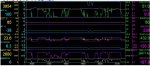
Last night I just kept adding input sensors to see what changed, until I reached the pile of wires above. And decided to quit before I shorted something out...
But it is cool to be able and setup all the input values how ya want em, and then watch how each change effects fueling and timing tables in real time. Rather than rummage through bunch of run log files, ya can just hold it at the rev limiter for hours and never burn a drop of fuel. Notice how it cuts the fuel back as approaches the limiter #.
My main goal is to test some slick tricks I plan to implement on these boat motors. Like rather than having a DSP5 switch, using the factory ABC, 2WD or 4WDHI/LO pedal modes under [torque reference] to control power and speed limits for the owner.
He wants a "valet mode" option per say that can be key locked when not at the controls. So basically gonna lock engines in Lo-range, and adjust tune limits accordingly. This way a single switch can easily control power level on both engines by just grounding a ECM pin.
But when ya start playing with all this data live, ya can easily get side tracked into, "what happens if I increase ECT or IAT2 values at WOT, and what table just caused this change??"
Attachments
Anyone have an idea of how one could take the FPR voltage and control a 0-5v signal to feed the FP sensor? Would really help if actual fuel pressure was tracking with desired.
You could always try something like this: https://m.ebay.com/sch/i.html?_nkw=Pwm+to+voltage&ssPageName=GSTL&LH_PrefLoc=3&_sop=15
Feed it the regulator pwm current and it will pump out pressure sensor voltage
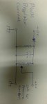
Or you can have the regulator pwm current charge a capacitor and feed off of it through a potentiometer to your sensor wires. You would need to experiment with different sized bleed resistors on the capacitor to get the voltage fluctuations you are looking for. I would try this method first. If that doesn't make sense I'll try and draw a back of the envelope schematic for you
Feed it the regulator pwm current and it will pump out pressure sensor voltage
Or you can have the regulator pwm current charge a capacitor and feed off of it through a potentiometer to your sensor wires. You would need to experiment with different sized bleed resistors on the capacitor to get the voltage fluctuations you are looking for. I would try this method first. If that doesn't make sense I'll try and draw a back of the envelope schematic for you
Last edited:
Many thanks. I might have enough parts to experiment on that. For now think I'll pick up a couple of these since price is right.
https://www.ebay.com/itm/1Pc-DC-1-8...h=item364132b8ef:g:~CwAAOSwfTVasPGA:rk:1:pf:0
https://www.ebay.com/itm/1Pc-DC-1-8...h=item364132b8ef:g:~CwAAOSwfTVasPGA:rk:1:pf:0
On the LB7, you could just invert the sensor table (like when swapping a LB7 -> LBZ with the fuel level sensor). Not sure if the newer motors have a table or if it is a hard coded formula. Hopefully it's a table, then your schematic would work fine.I just realized the circuit I drew up is backwards. And would increase the "pressure" as the "regulator" was closed. Might be able to fix it in the tuning though
Might have to play with the time constant of the RC filter so it doesn't end up oscillating or freaking out the PID control in the ECU, but otherwise should do what he needs.
Hmm, thinking about it, is the regulator ground side switched? I think it is on the LB7. Wouldn't be hard to tweak that schematic to make it work. Might actually simplify things, as you'd charge the cap off 5V then bleed it down with the regulator signal from the ECU.
Is this design of use?
http://webcache.googleusercontent.c...cd=1&hl=en&ct=clnk&gl=us&client=firefox-b-1-d
If I recall, all of the input signal lines on the E35 units will accept PWM or DC by default. Then we'd only need to switch the duration correct?
http://webcache.googleusercontent.c...cd=1&hl=en&ct=clnk&gl=us&client=firefox-b-1-d
If I recall, all of the input signal lines on the E35 units will accept PWM or DC by default. Then we'd only need to switch the duration correct?
I think your right. The +12v is continuous and it is the ground side the is switched. Dont think that will make much of a difference though as it is just charging a capacitor and then you are drawing off of the cap and then dropping it down with a voltage devider resistor set up.
May need to throw another diode or two im there somewhere too. Either that or isolate it with a small transformer. Could likely use a toroidal inductor and wrap a secondary on it for the 5 volts that feeds the capacitor.
May need to throw another diode or two im there somewhere too. Either that or isolate it with a small transformer. Could likely use a toroidal inductor and wrap a secondary on it for the 5 volts that feeds the capacitor.
Is this design of use?
http://webcache.googleusercontent.c...cd=1&hl=en&ct=clnk&gl=us&client=firefox-b-1-d
If I recall, all of the input signal lines on the E35 units will accept PWM or DC by default. Then we'd only need to switch the duration correct?
It would work but it looks as if that circuit assumes that the source has little to no current available and it is just sampling the PWM signal. I would think a resistor would be needed to at least keep it from throwing a code
You could use the Arduino to do all of it without the opamp. I cant imagine that the pressure sensor circuit on the ecm is that low of impedance that it exceeds the capability of the Arduino. All you need is some code. I'm not too familiar with Arduino code, having only played with it a few times, but couldn't you sample the PWM on an input pin and with some code output a desired voltage on another pin?
If the ecm can except a PWM signal right into the sensor input couldn't you feed the PWM through a 2:1 transformer and invert the wires to the sensor input? If the frequency of the PWM is high enough it should pass through a small ferrite transformer just fine. If it cant handle the PWM on the sensor input then rectify it, add a cap and feed it in as a straight DC and fix the voltage relationship in the tune
Last edited:
Thanks.
Yes if there is enough memory to handle the job I believe it could. However I suck coding, but do solder.. lol.
It would be nice to build a board that adjusts multiple signals based on throttle. So when you press the throttle, boost, temps or anything else you wanted increased with it.
Sent from my SAMSUNG-SM-G890A using Tapatalk
Ah, yeah. Without boost, or is it MAF, maybe both it won't run right. I forget but does the MAF run with a PWM too or is it a analog voltage? I'm pretty sure the boost is an analog signal.
Is there anyway to use the injector voltage to drive the boost and MAF sensors? Using a similar circuit to what we are already discussing but with a much greater ratio (5:1?) on the transformer? If so it would be a "zero lag turbo" at what ever size you desired :woott:
Is there anyway to use the injector voltage to drive the boost and MAF sensors? Using a similar circuit to what we are already discussing but with a much greater ratio (5:1?) on the transformer? If so it would be a "zero lag turbo" at what ever size you desired :woott:
Last edited:
The MAF A/D converter will accept PWM or analog. Setting is in the standard tune tune library. Even have a 12k Hz scaling CAX file I need to test to improve range. However the tune I'm currently playing with has MAF disabled. And while runs great, I noticed that effect the SAE.LOAD pid data. The ECM now only calculates load up to 50%. Interesting..
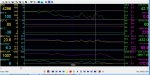
Check out this 3 second capture of the ecm responding to an over-rev limit situation when throttle remains pegged and rpm doesn't drop. It starts out only pulling about 10% of fuel [PW & MainIQ], then gives it back. Next time it pulls a little more PW and IQ, but starts reducing FP also. The Load value keeps stepping down also. Till finally it just says "screw it, cut everything."
Check out this 3 second capture of the ecm responding to an over-rev limit situation when throttle remains pegged and rpm doesn't drop. It starts out only pulling about 10% of fuel [PW & MainIQ], then gives it back. Next time it pulls a little more PW and IQ, but starts reducing FP also. The Load value keeps stepping down also. Till finally it just says "screw it, cut everything."
Attachments
Thats pretty interesting. Did it throw any codes? Did it resume normal operation after letting off the throttle and reapplying it?
For MAF input, I assume analog would be easier as trying to make a frequency adjustable signal that follows some logic may be a bit more work. But a simple rise and fall of a DC voltage could be done quite easy
For MAF input, I assume analog would be easier as trying to make a frequency adjustable signal that follows some logic may be a bit more work. But a simple rise and fall of a DC voltage could be done quite easy
It recovers fine soon as RPM drops below 4200, even without lifting throttle.
I've still got a few trouble codes, but nothing related to these issues. Next I'd like to hook up my 16ch scope tool to the injectors and see if they pull fuel by bank, injector, or evenly across the board.
I've still got a few trouble codes, but nothing related to these issues. Next I'd like to hook up my 16ch scope tool to the injectors and see if they pull fuel by bank, injector, or evenly across the board.
Stuck a 1000 ohm resistor in each injector plug, and ECM still setting circuit codes. So needs more work there to make happy, but it doesn't seem to care cause at least it's firing those imaginary injectors.
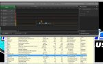
Connected my little digital scope leads up to a few of those resistors and cranked it up to 3800rpm. A 3900us main pulse, no pilot, says 12.8% duty cycle at that RPM. Sound correct?
Had to enable a glitch filter to clean up the injector signal since it's not a true square wave pattern. When using a "good" scope you get a better view of how it slopes off the power. But for now channel 3 to channel 4 pattern comparison gives you a general idea how they look raw.
Also noted that ECM is adding or subtracts up to 150us to each individual injectors pulse, even though it reports as 3900us. When I get a min I'll jack that rev limit up to high as will go, and see if I can max that duty cycle out.
Attachments
You are going to need something like a 1 or 2 ohm resistor to trick the ecm if it will even do it. Like I mentioned earlier, I wasn't able to do it with a resistor but got an inductor to work. Granted it was an LB7 and not an LMM, but they are both solenoid injectors though