Im going to start a new little discussion segment/forum in my vendor section on Duramax Diesels.
As everyone knows, I get a kick out of electronics and whiz-bang little gadgets that are related to trucks/automotive stuff. I think it really interesting the electrical engineering, electronics design, and computer technology that goes into the simplest of things in cars/trucks nowadays.
I like explaining things, I like figuring out how things work, and I like sharing my knowledge about things that interest me. So I figured I would start a series of threads where Ill take something apart, maybe describe a little bit about whats going on, and if anyone has questions, Ill try to answer them. Im just a stupid dumbass liberal-arts major; Im not a formally-educated electrical engineer or computer-science engineer so Im not going to have all the answers....but Ill at least have some pretty high-resolution pictures for you guys to look at.
Its going to be creatively called the...wait for it..."whats inside" segment.
OK. Here we go.
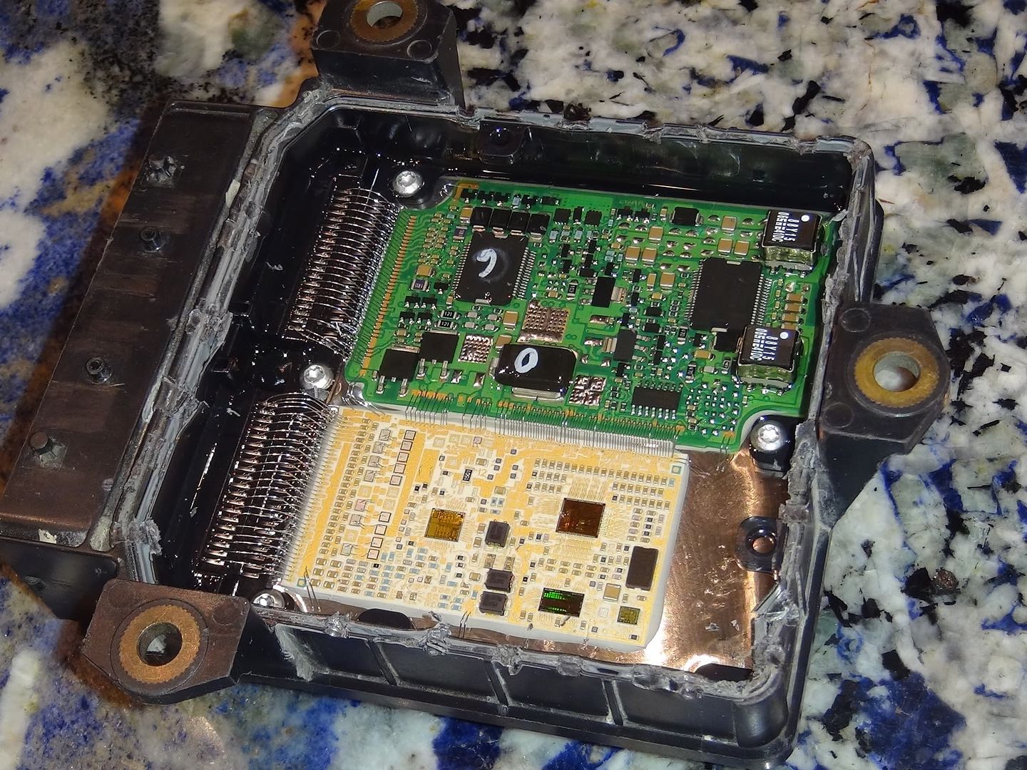
For starters, the thing was designed to be assembled once and never taken apart. It is sealed/glued together. I had to spend a few minutes looking over it just to figure out HOW to open it. The only reason I took this one apart was because it was dead. Not "dead" as in it was flashed wrong and now nothing will communicate with it...but actually physically damaged internally...There is an internal short somewhere in the power supply or ground circuit because when plugged in, it doesnt even draw any current.
So I pried it open.
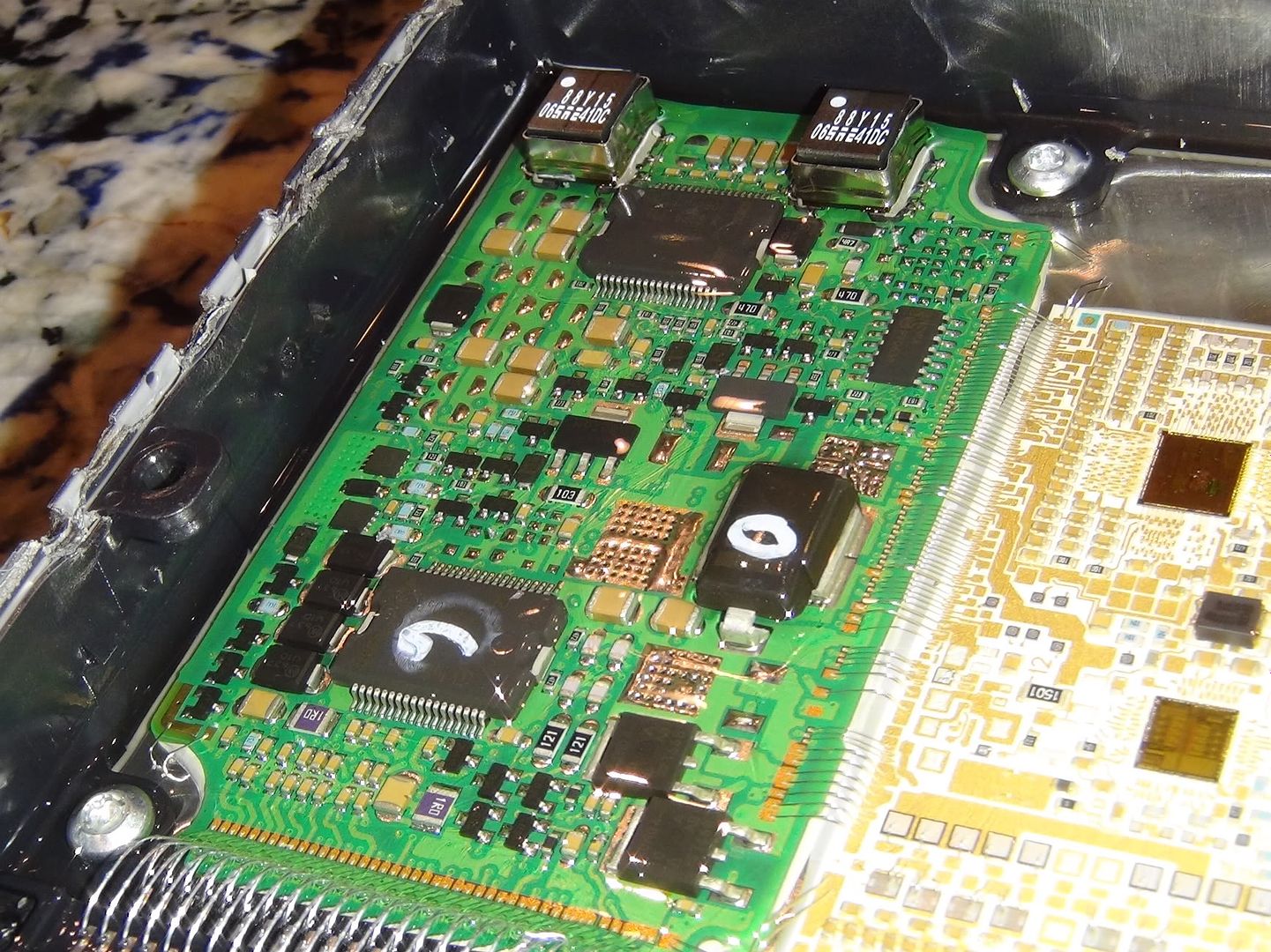
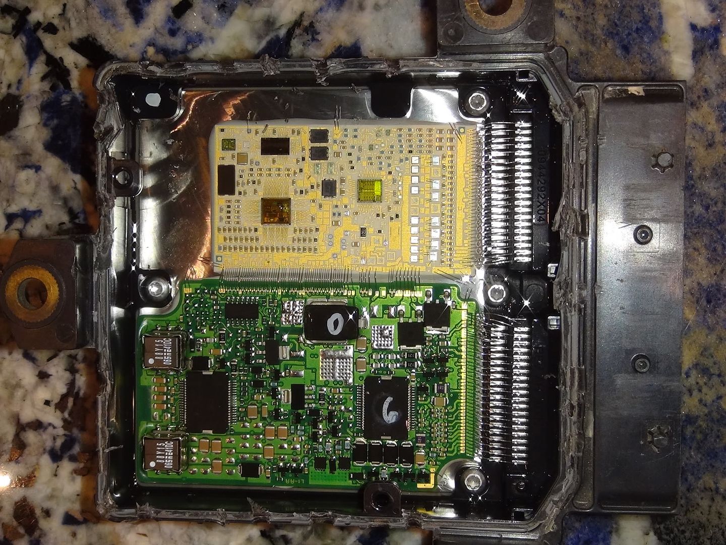
The whole PCB (printed circuit board) is potted. What that means is its fully encased in a sort of epoxy to keep it 100% liquid and air sealed...and to protect against vibration. The potting stuff allison used is something like a mixture of jello and rubber cement. Its squishy but not sticky, and its not hard. Some sort of gel, I dunno.
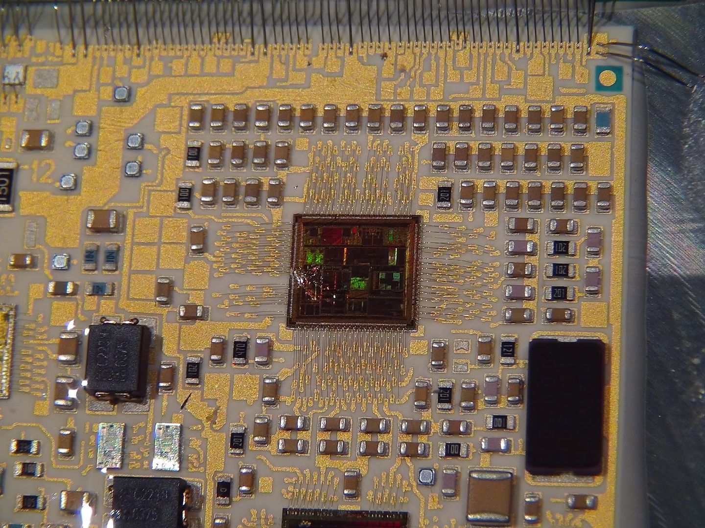
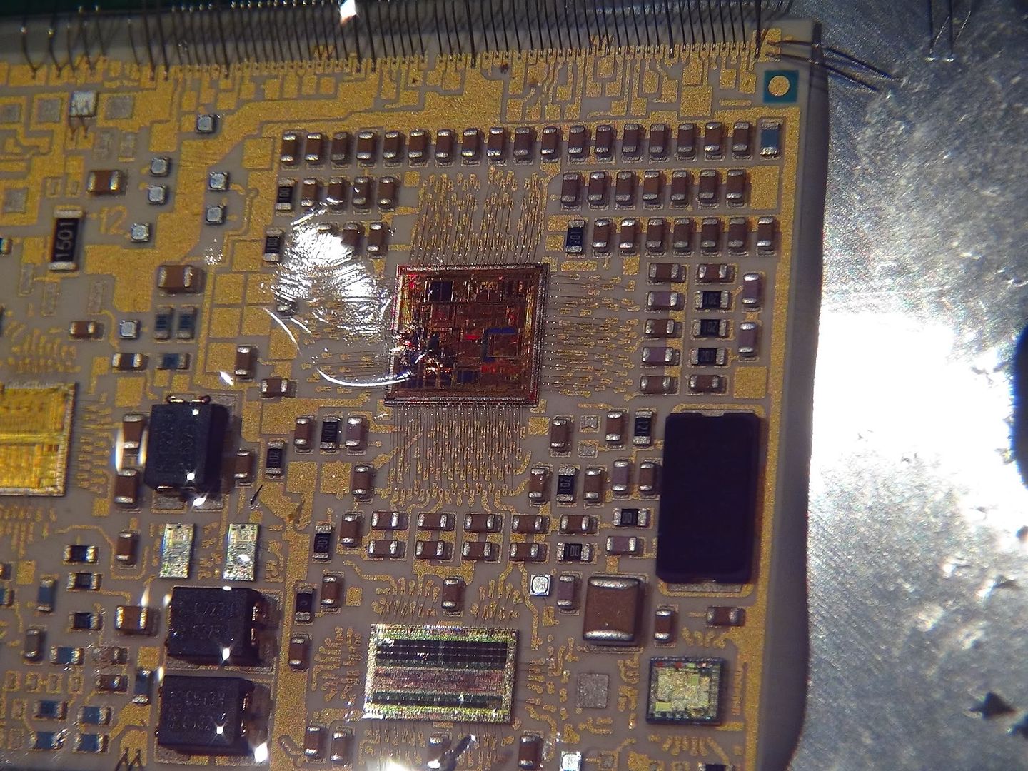
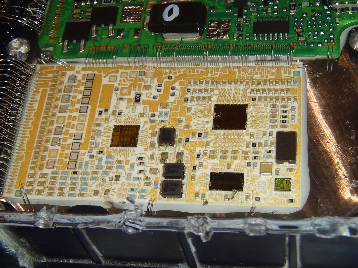
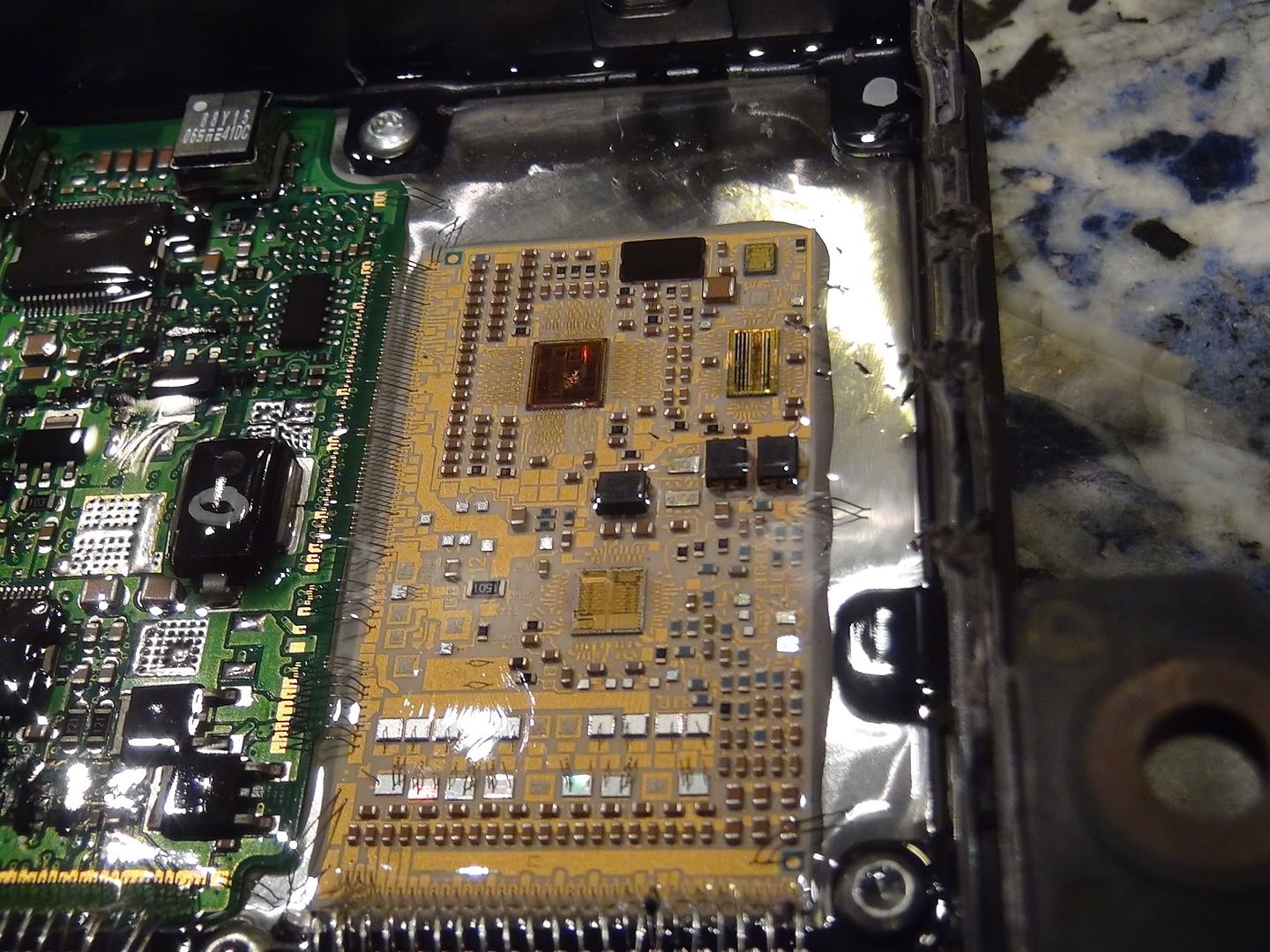
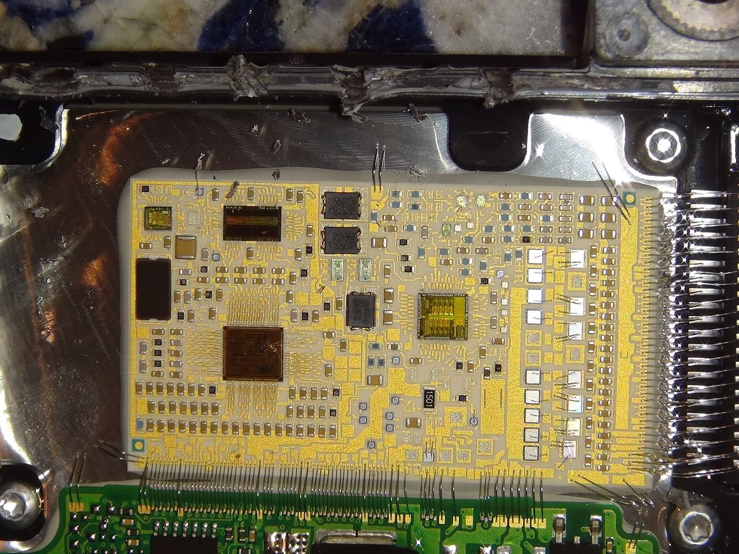
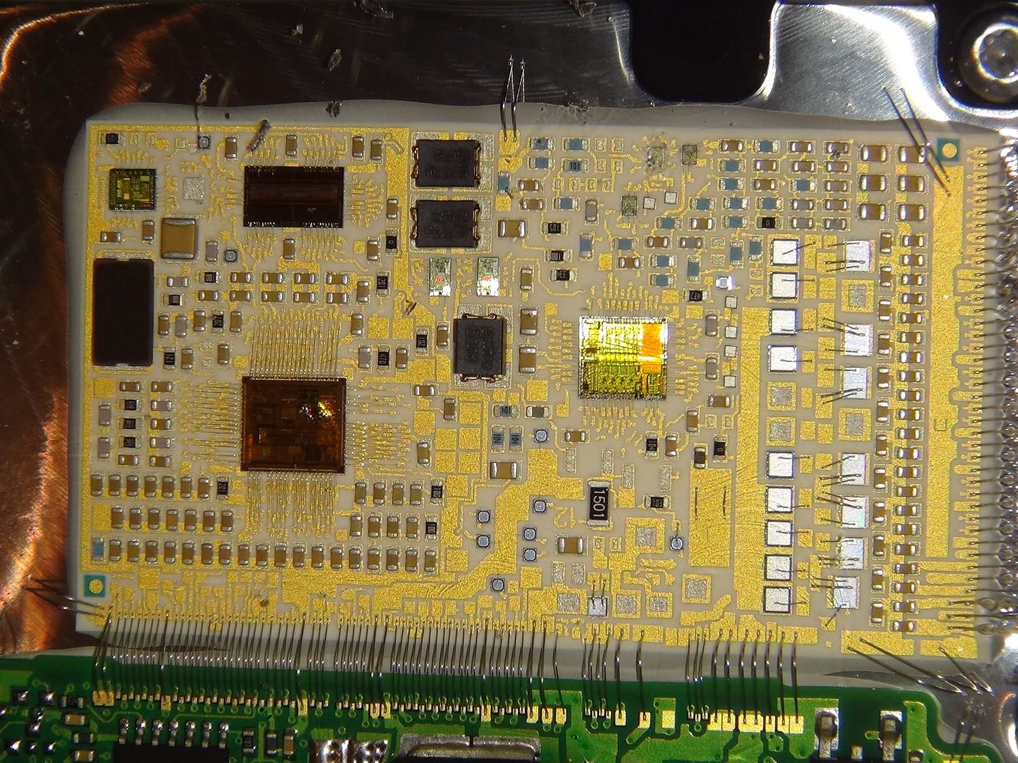
You can see the tiny wires that connect the two boards together...these wires are "floating"/suspended in the gel potting compound. They are incredibly small and delicate. Both PCB's are mounted solidly to the big heat sink, which has the spiky fins on the other side that we can see on the outside.
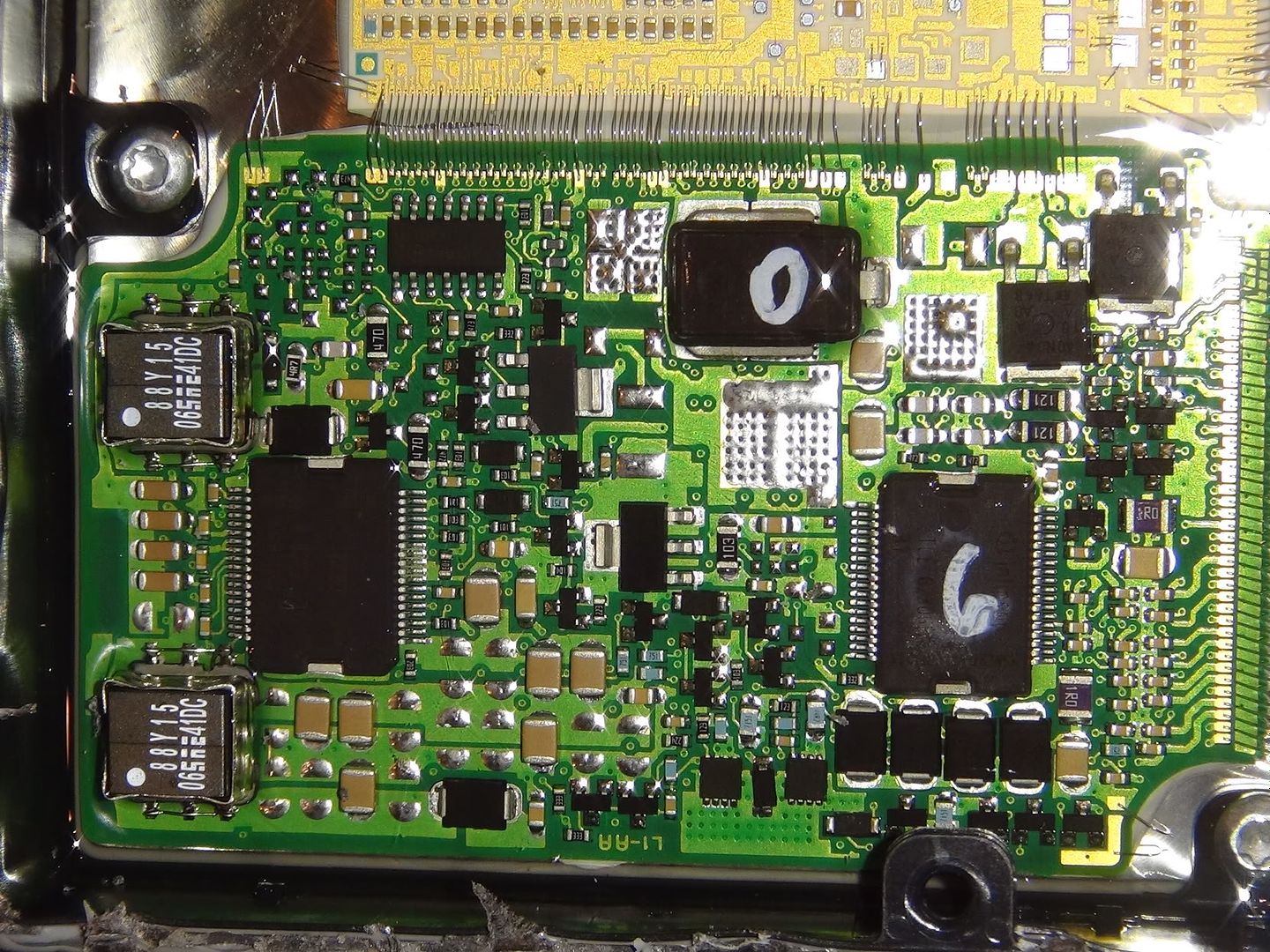
Its divided up into two separate boards. One is the controls and the other is the drivers. Basically one side is the brains and the other is the muscle (to drive the solenoids and stuff). The green PCB is the driver board.
Later, ill make some diagrams pointing to various objects and what [I think] they are. Fingers will probably be able to make more sense of this than me, but I still find it cool to look at just the same.
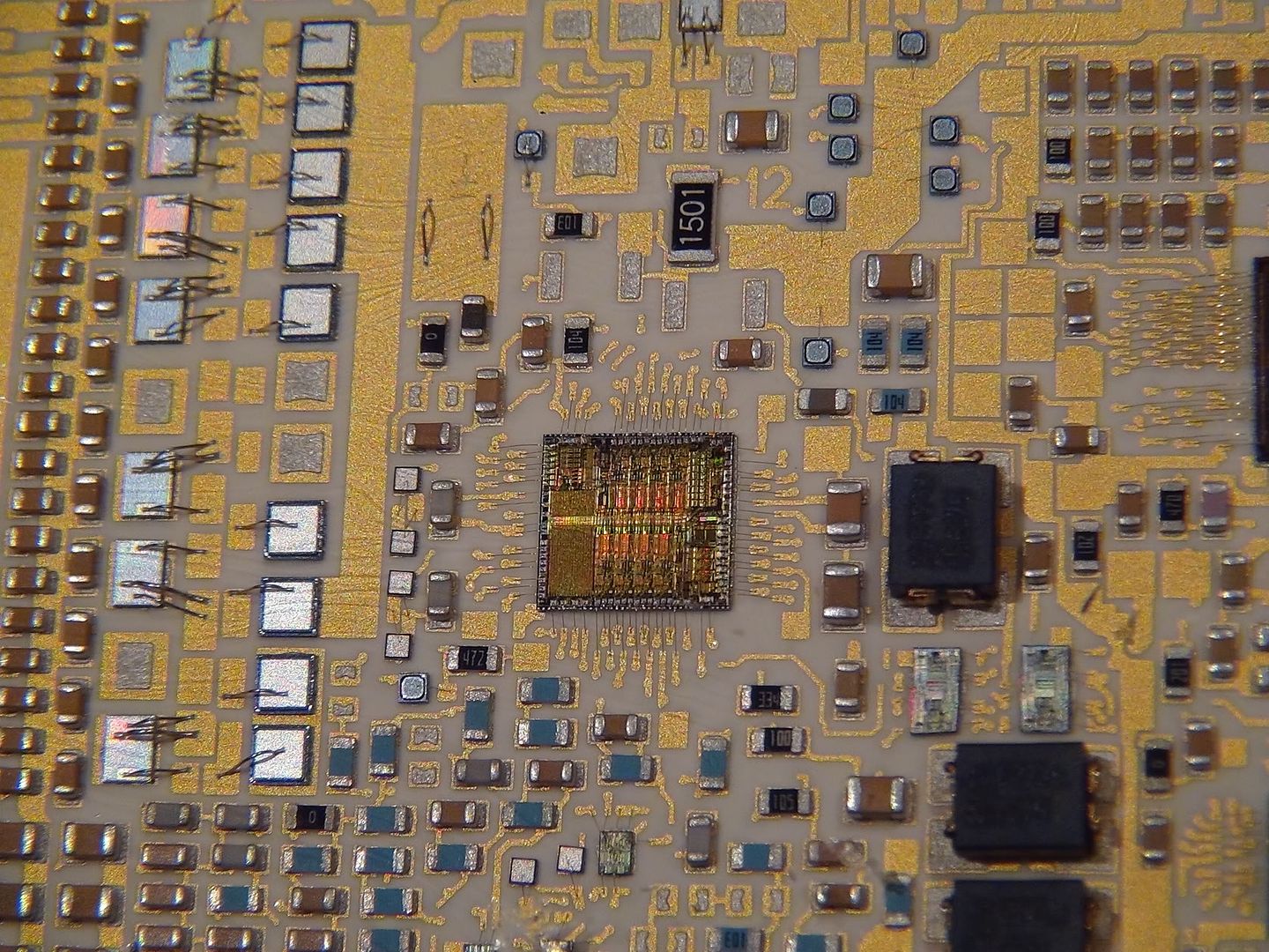
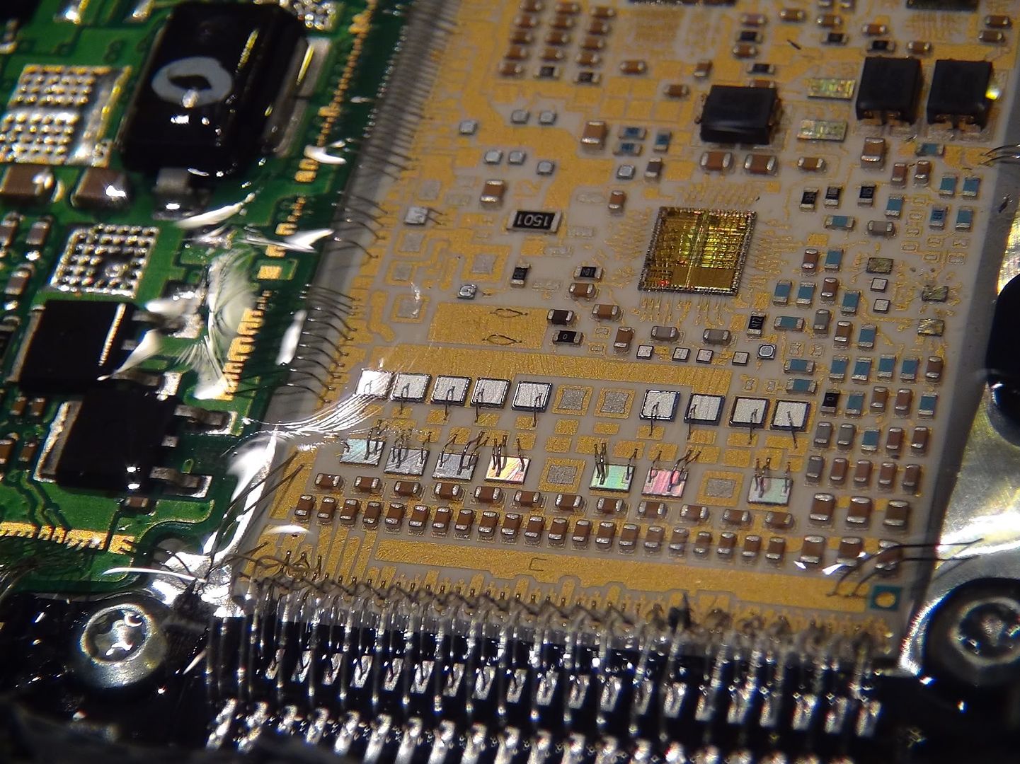
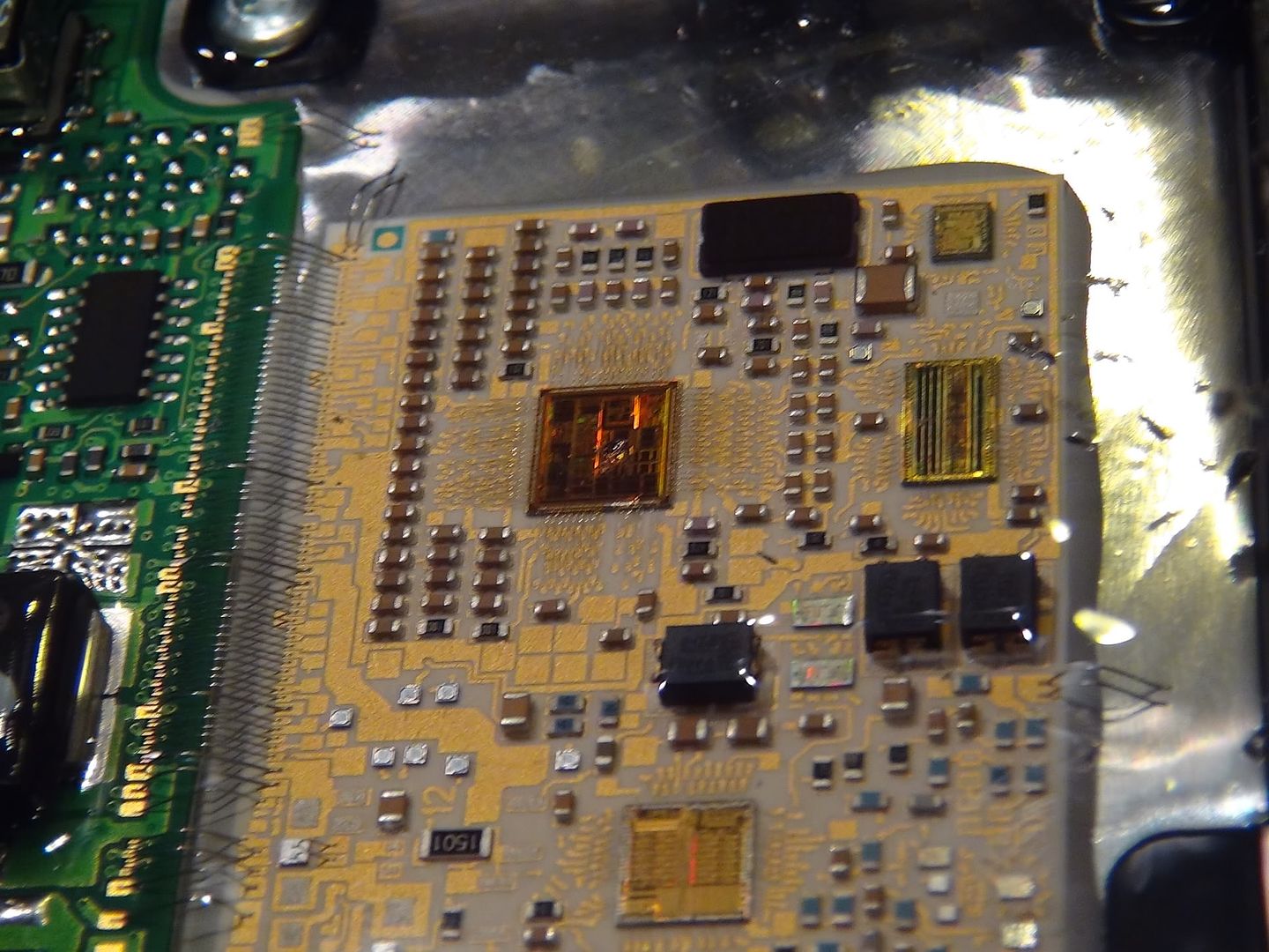
The processor cores on the tan/brown board are exposed, as you can see. They are holographic-looking things and when you tilt the TCM side to side, they change color and look 3D..very cool.
the pictures are big so you can really look up close. Even if you arent an electronics person, its still interesting to see the detail and how small/detailed some of the stuff is.


