Episode 13:
One thing I forgot to add to the last update: I hadn't driven the MBRP Dirtymax in a while as I was working on this truck, but the opportunity came up to drive it at the last 2 events of 2012. We ended up winning the World Championship in NHRDA Pro Stock!
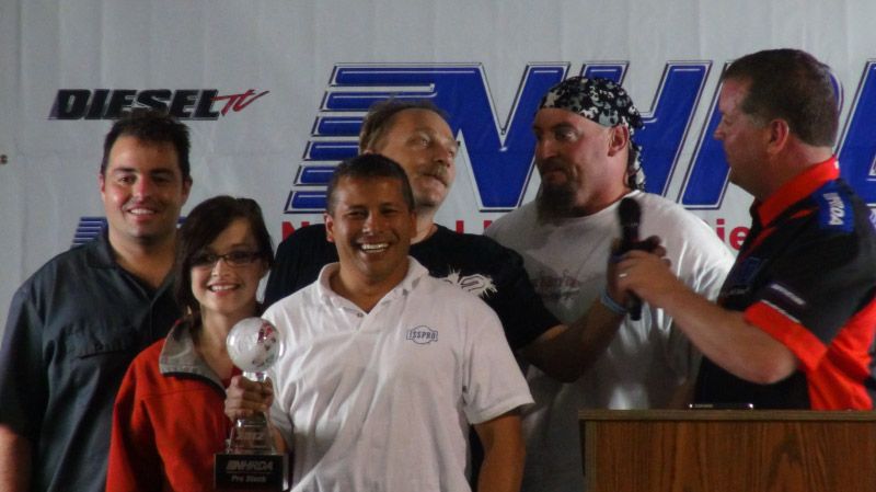
The coolest thing is that over 40 million viewers tuned in to watch the event on Fox Sports Net! While that's great for the sport, I have to remember that it's probably a small fraction of the people who watch Honey Boo Boo (and no, I never have)...
A couple more sponsorship-related items:
Would you please "Like" our ISSPRO facebook page? It will help show the bosses that sponsoring this truck is a good thing! http://www.facebook.com/IssproInc
We are happy to announce that Mahle has signed on as an Associate Sponsor, and we will be running Mahle pistons in the truck. Don't tell them, but even without sponsorship help I would have gotten their pistons anyway
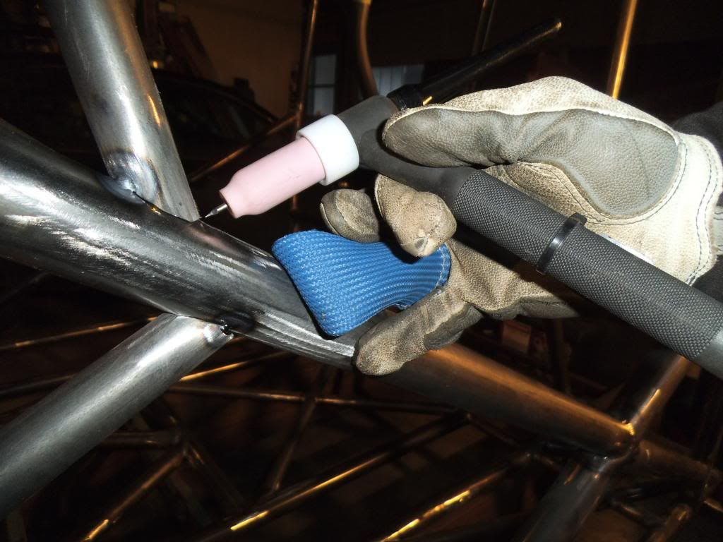
After all that excitement it was back to the garage! As I started finish-welding some of the junctions of several tubes, I found that I had to extend the TIG torch's electrode so far out that I didn't get good shielding gas coverage. I had planned to pick up a "gas lens" for the torch, which is something that focuses the flow into a nice even column of gas. I ended up getting a specific version of the gas lens called a CK Gas Saver, which is designed to work well at reduced argon flow rates (saving some money in the process). It was also cool that its cup for the shielding gas is a clear pyrex-type glass, giving better visibility of the arc and puddle.
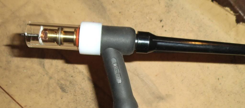
I tried it out and it was awesome! Unfortunately it was also breakable, and I set the torch down on the jig to grab more filler rod, and it slid off and broke! I ordered some spare parts and got it back together. This thing would have already paid for itself in reduced gas costs, had I started using it at the start of the project. Heck, it is worth it in reduced blood pressure from trying to make some of those long-reach welds work!!!
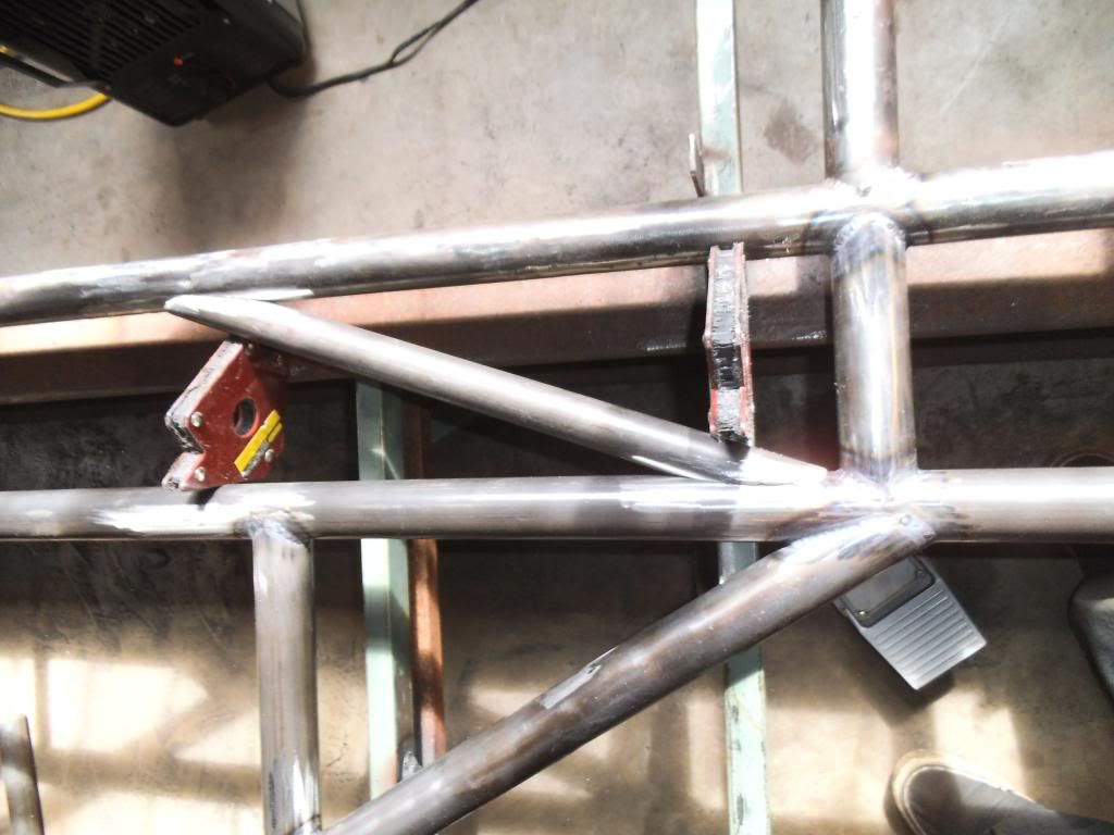
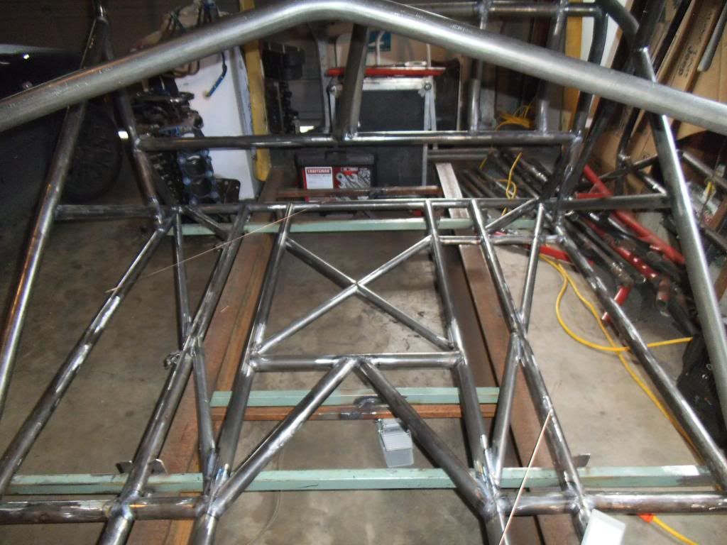
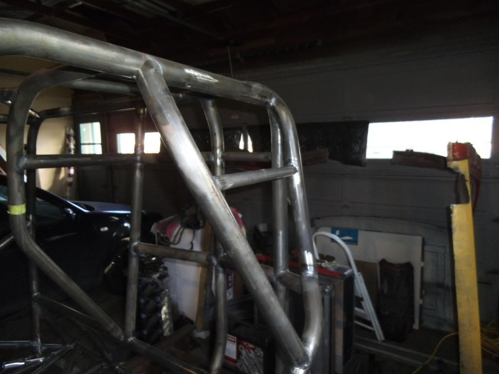
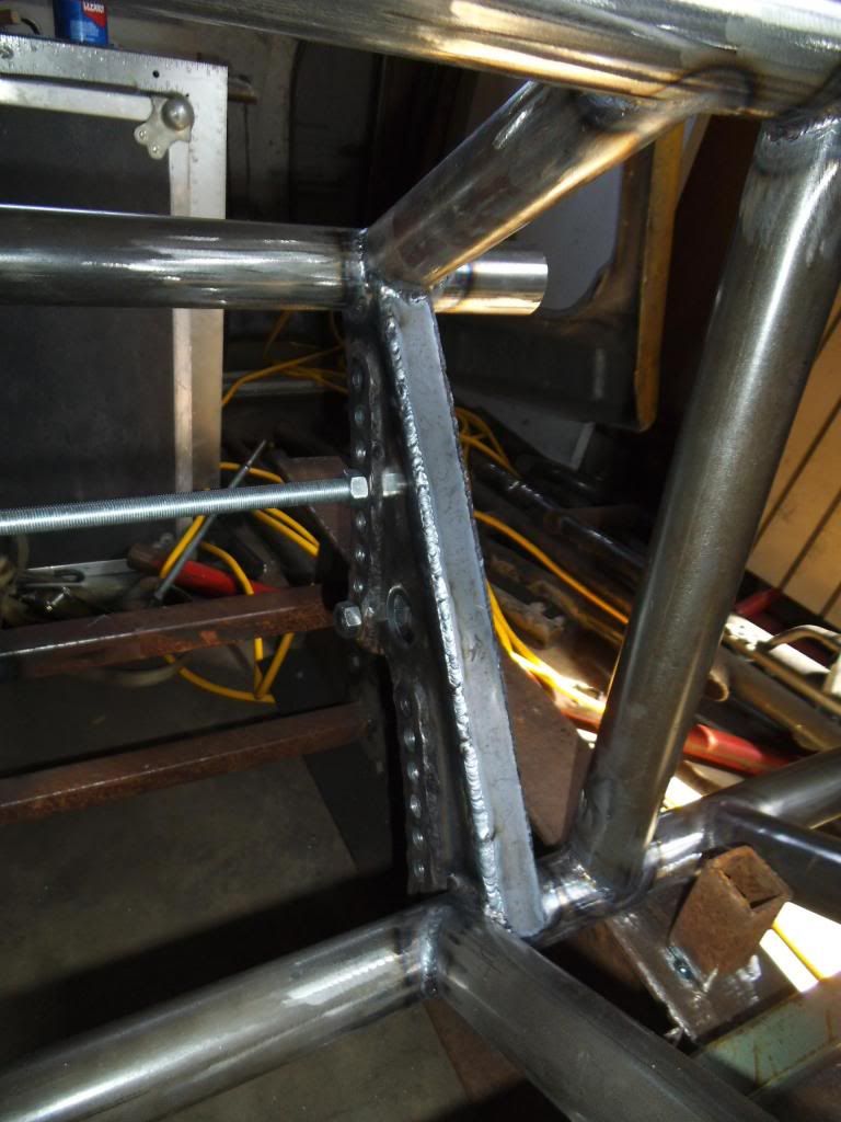
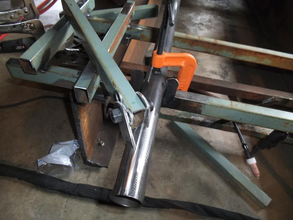
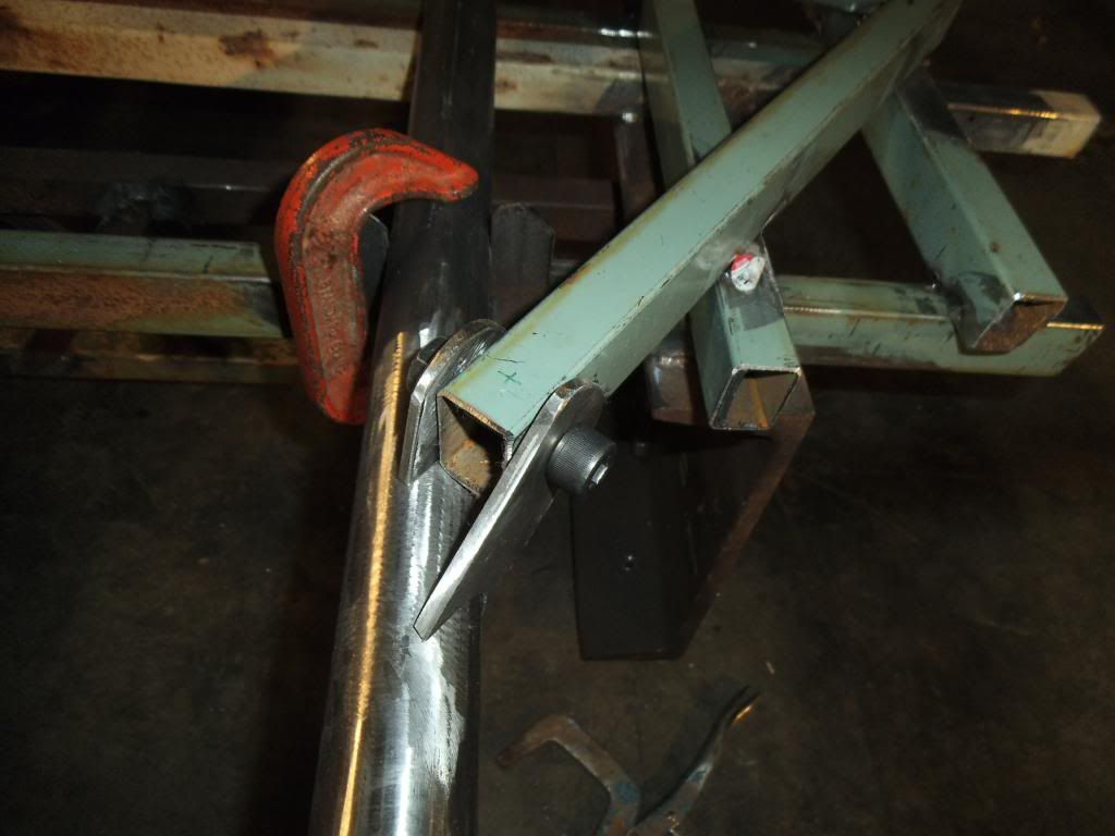
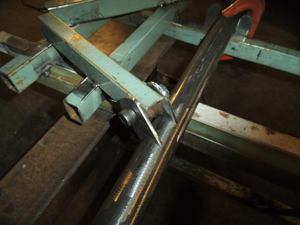
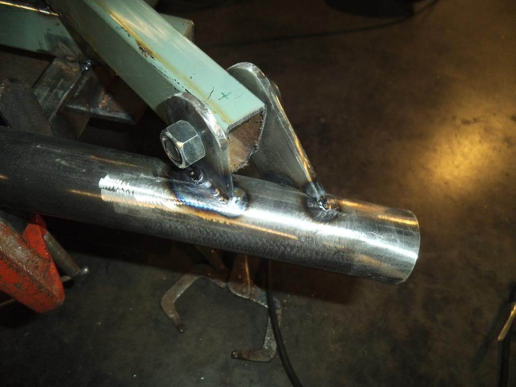
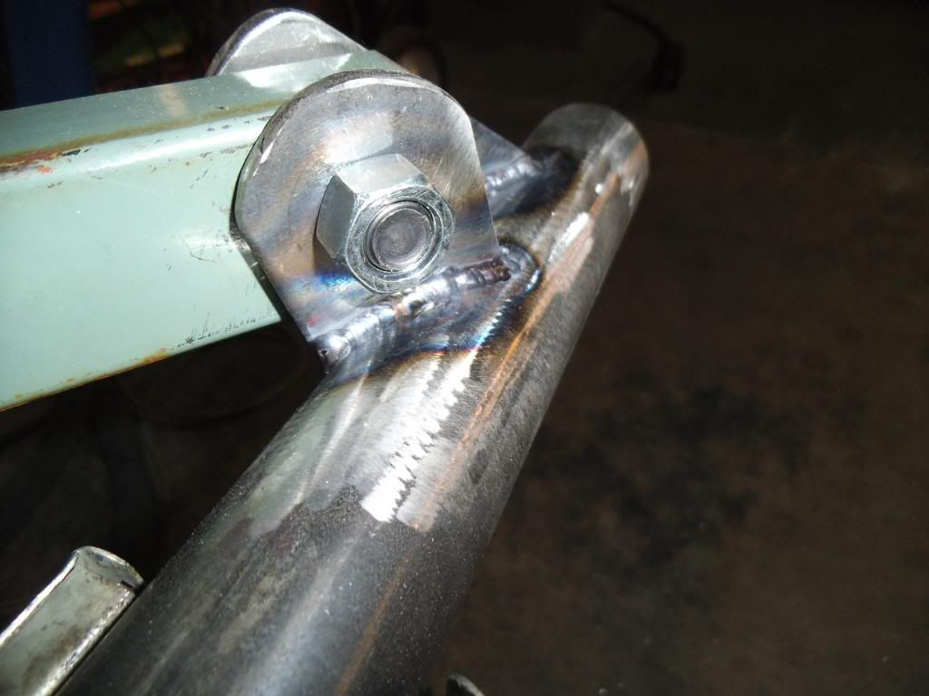
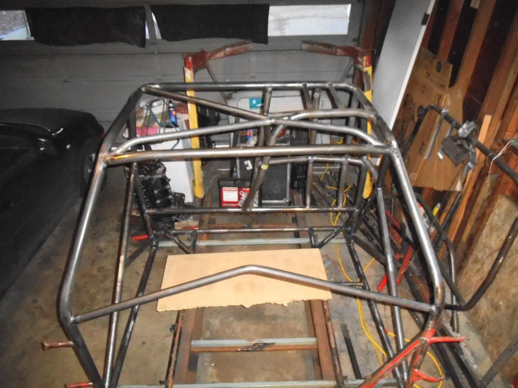
Next up I installed the "X" braces across the roof of the cage. The corner mounting points resulted in some weird complex angles, so the tube end fitting was difficult and cumbersome (but then again what HASN'T been on this build???).
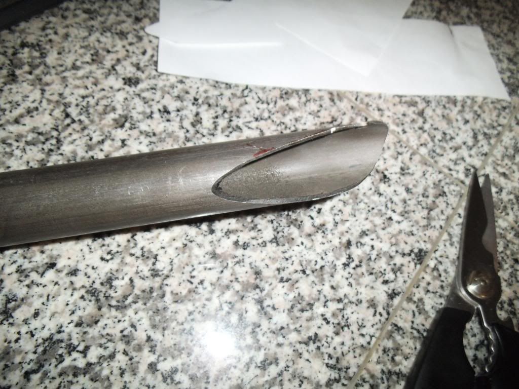
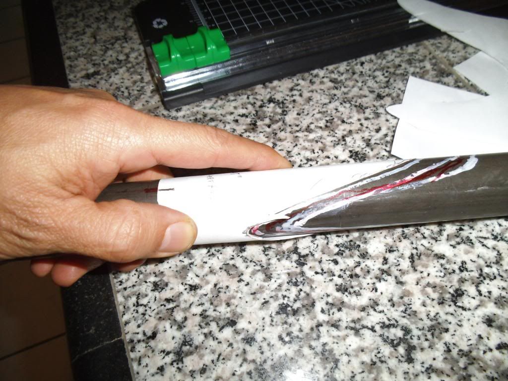
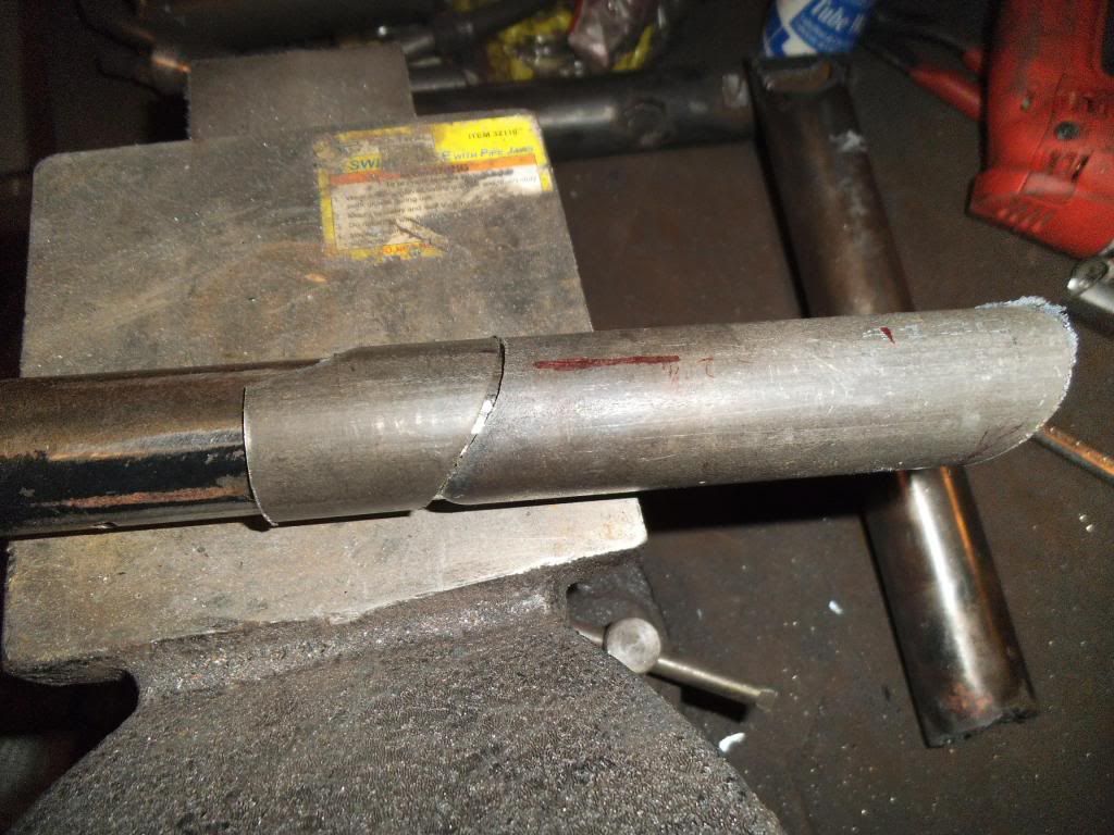
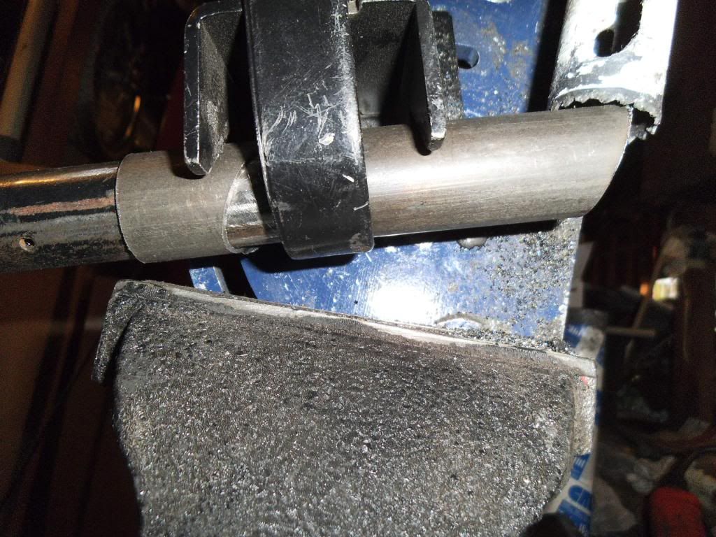
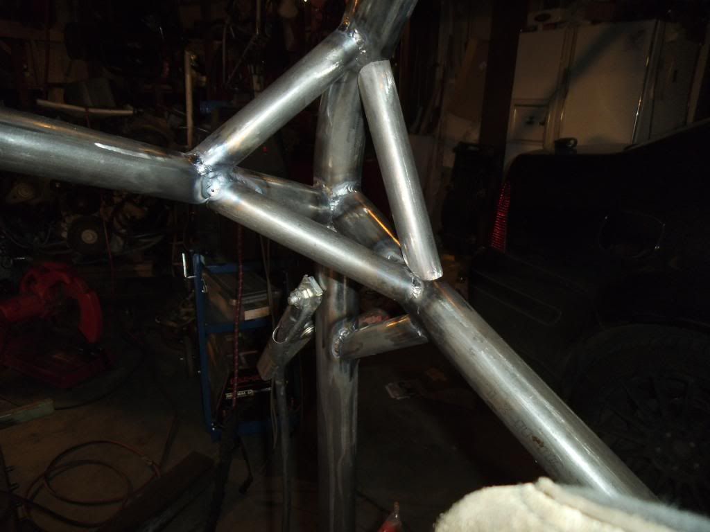
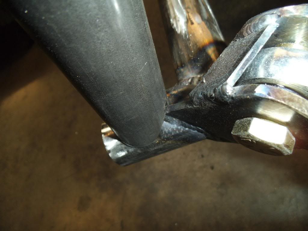
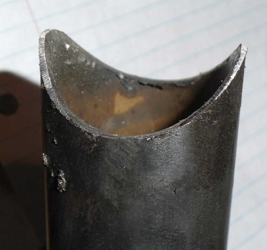
One item on tube fitting that is worth mentioning: when you use a notcher to cut the contour in the mating tube, the farthest forward edges end up downright sharp.
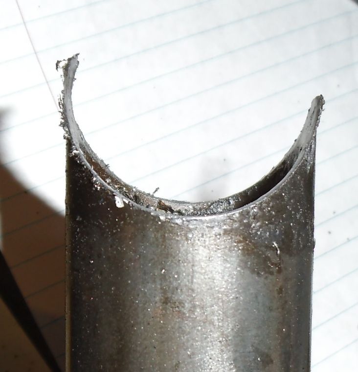
As I discovered early on, if you don't "blunt" those edges with a grinder, you end up with a very thin section when you weld, and if the weld puddle is at the edge of the tubing you will end up with a hole as the thin section melts away. By blunting the edges you move the weld location to where the tubing is full thickness.
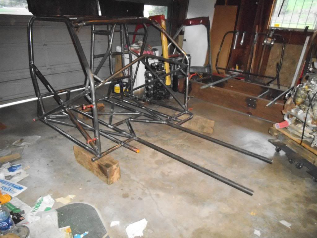
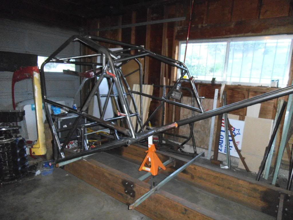
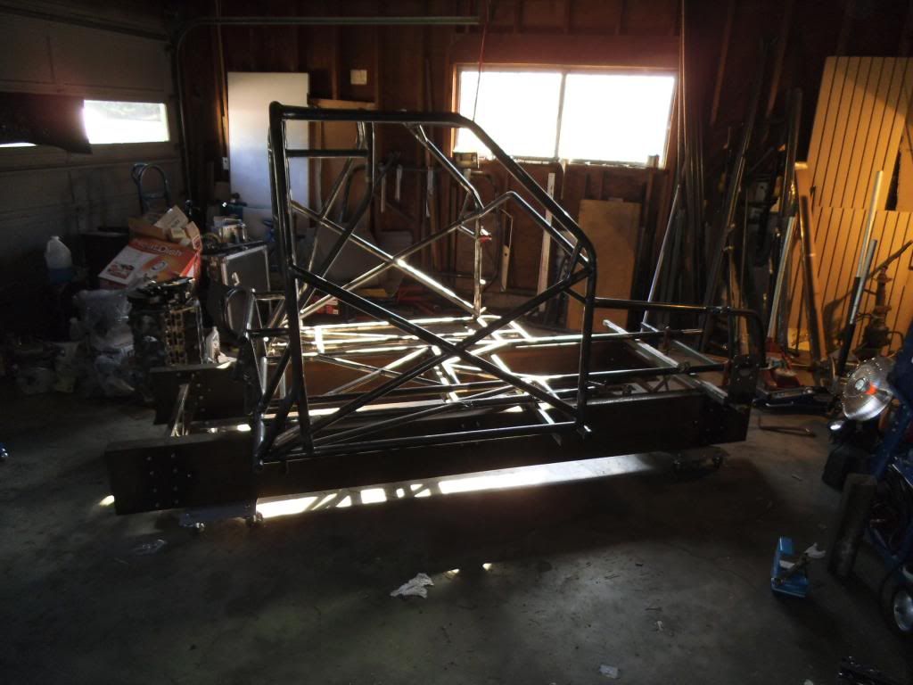
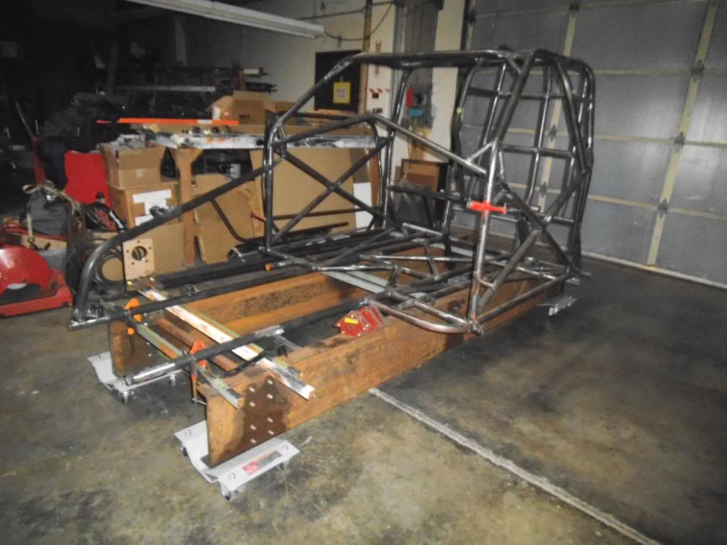
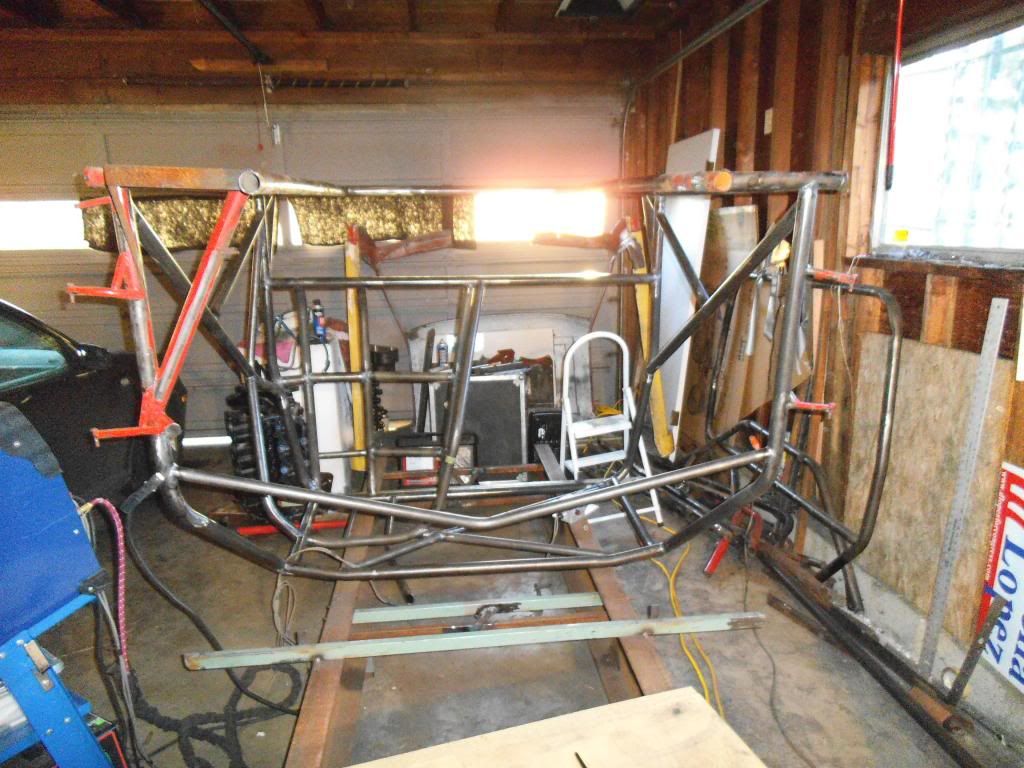
I decided to go ahead and flip the chassis over and get at all the weld spots I had skipped to this point. Once I add the front of the chassis it will be a lot harder to flip and maneuver in my little garage!
I removed a diagonal from the firewall area, as that section will be extended to give me more room for the pedals. It was nice to have my plasma cutter working well again, having replaced a worn out electrode!
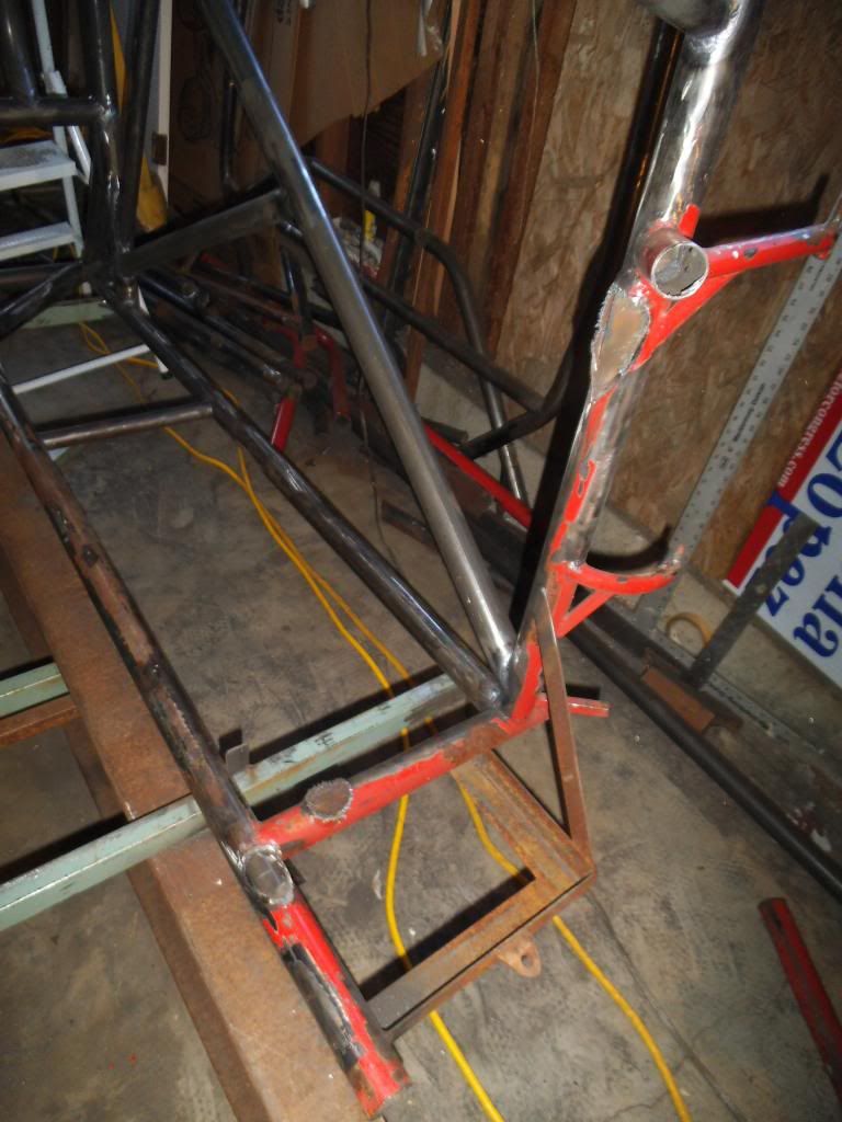
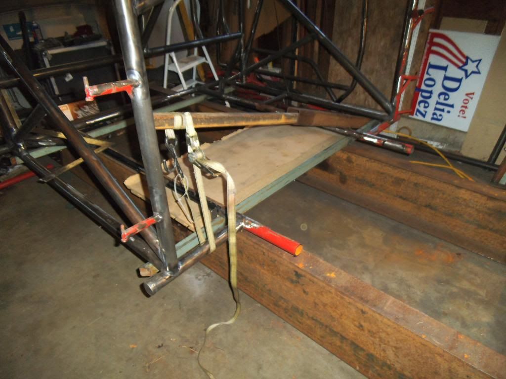
With that diagonal out of the way, I found that the section of the original floor had a twist to it, and needed a little "persuasion" to get it flat:
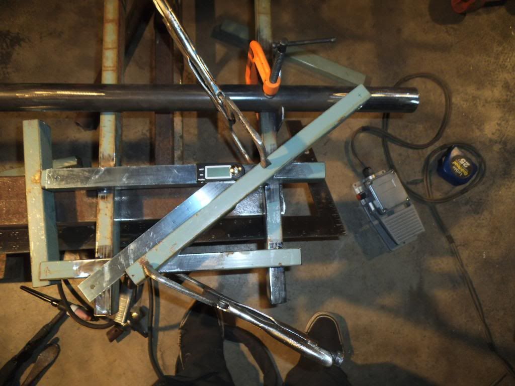
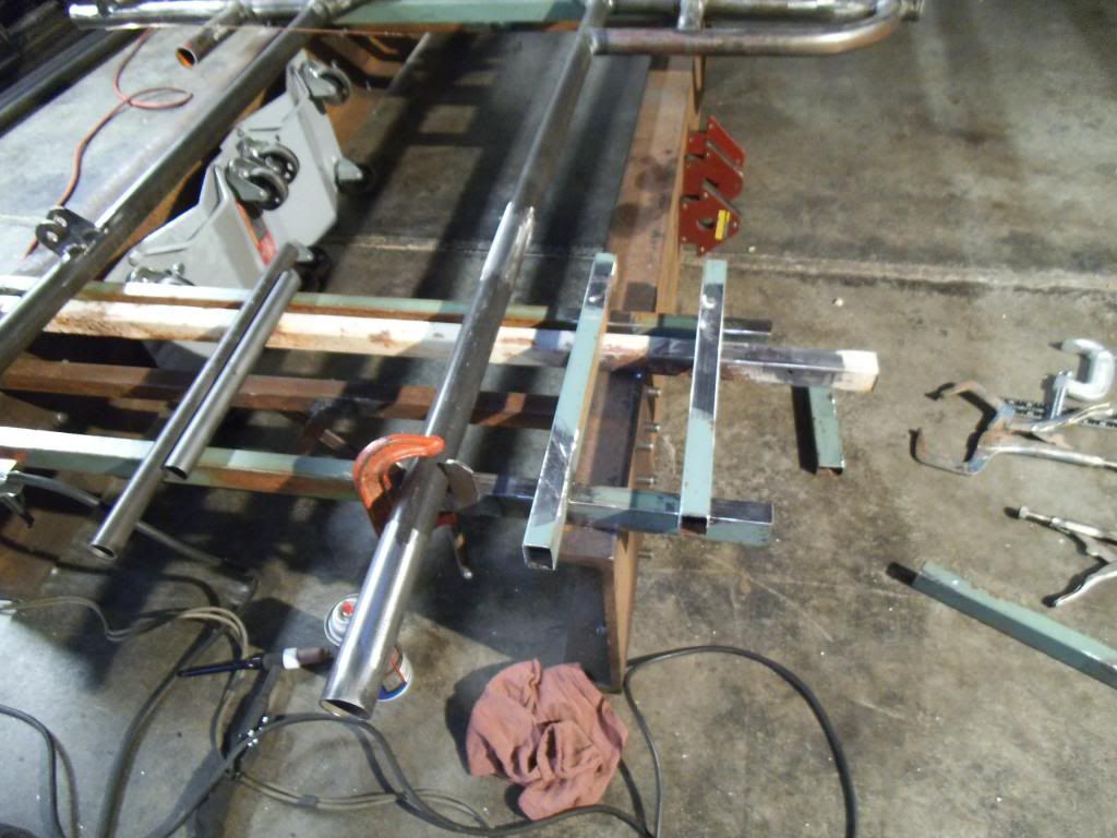
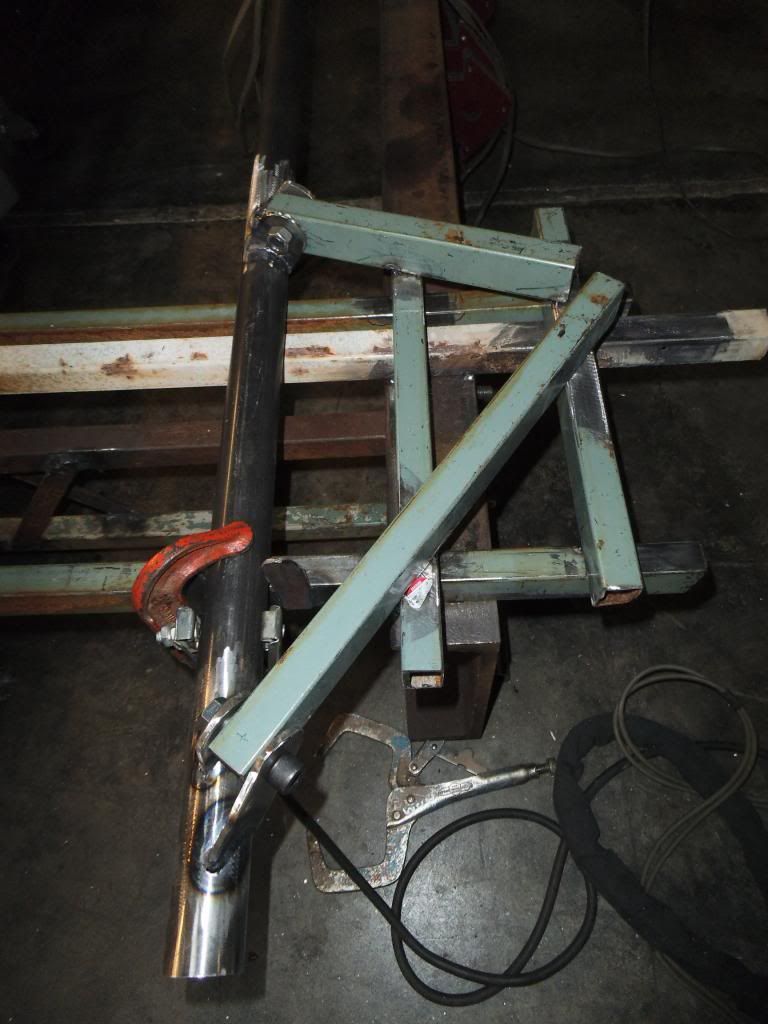
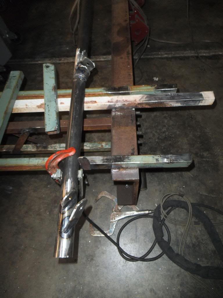
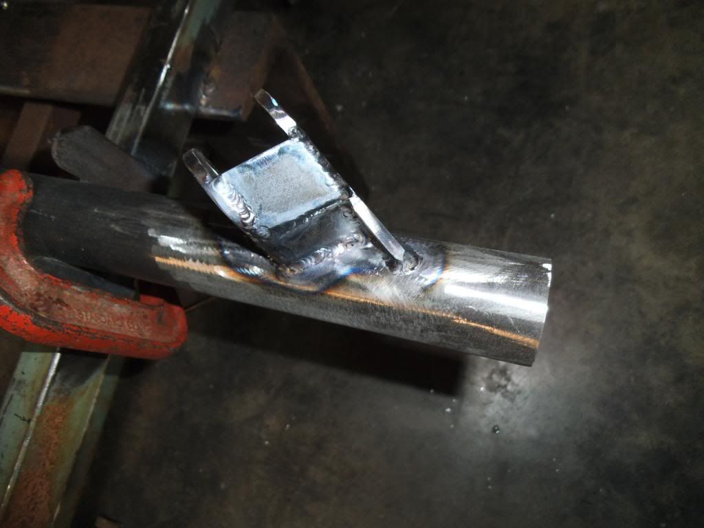
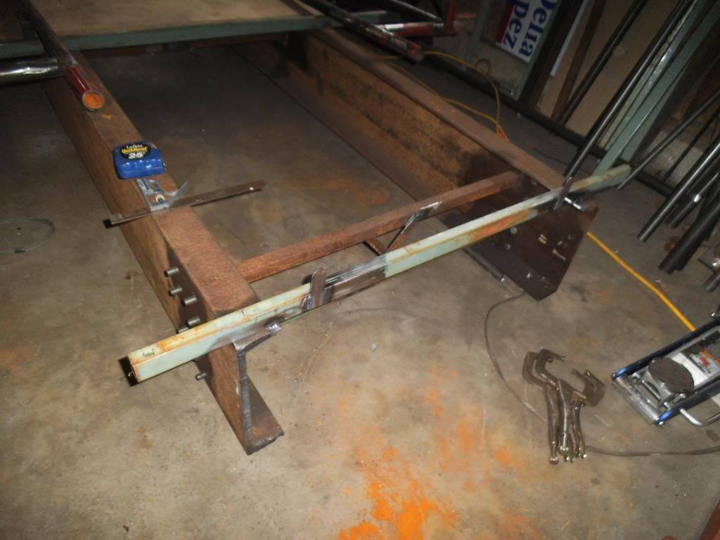
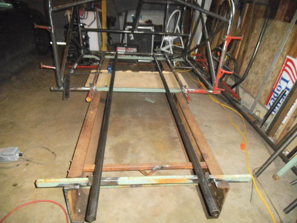
I added a new crossmember and alignment tabs for holding the front frame rails into the jig.
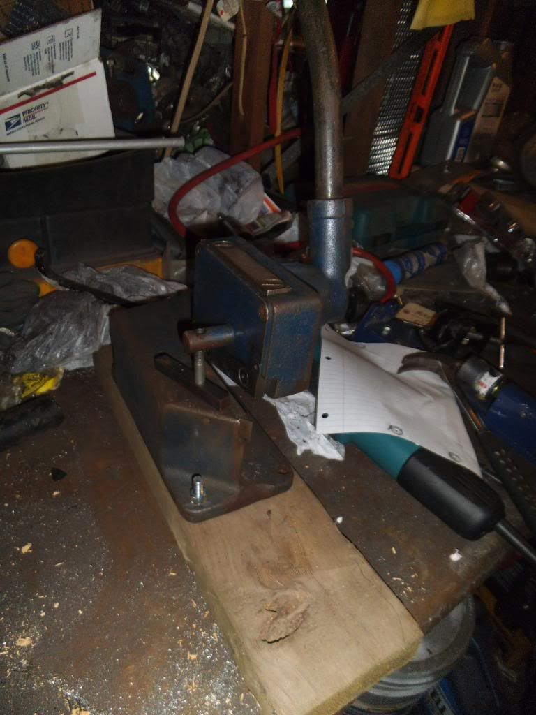
One of the things I am trying to do is come up with quicker ways of doing some of the repeated tasks in this build. One of those tasks is cutting small strips or plates of metal, either for the jig or for brackets on the chassis. When I built my gasser chassis many years ago I borrowed a Whitney shear and punch from my family business, which allows me to make short work of many of those tasks. I went ahead and found used versions of the same tools on ebay to use for this build.
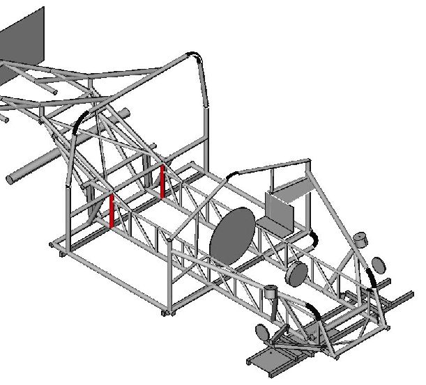
As I started laying out the details of the floor area, I decided it was worth it to lay it out in CAD so I had a better starting point for the measurements and angles of the tubes I was going to be cutting and notching. I was hoping to do this in a solid CAD model, but I hadn't touched a solid/3D CAD program in MANY years! I had been using a freeware 2D program for the last several years to do simple stuff like laying out the rear frame of my small block Vega, and designing the parachute mount for my big block Vega. I found a decent solid modeling program with a free demo, but was still learning it and decided to just get it done in the 2D program I was familiar with:
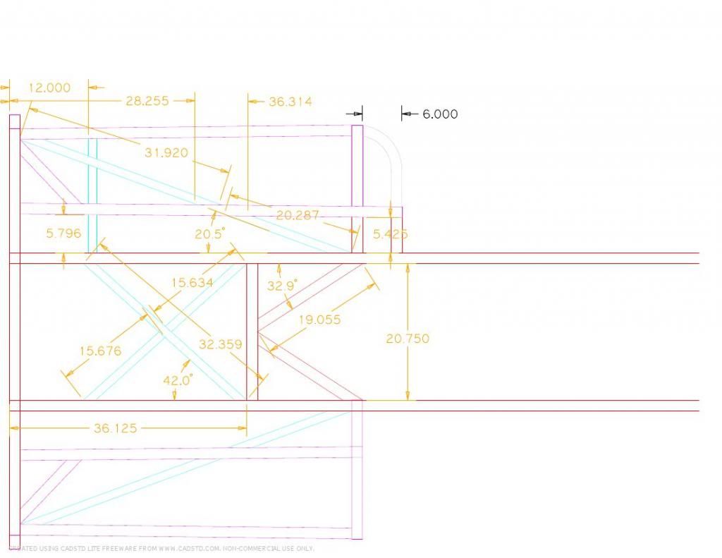
I discovered that the freeware version didn't allow angular dimensioning, but the "Pro" version was only $37.50, and I've gotten waaay more utility out of their package than that over the years!
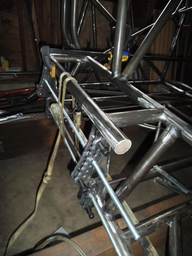
As with the prior spreadsheet I had used to organize the tubes I needed, this would help me optimize the cuts so I could get the most usable tubing out of the lengths I had. Plus it was something to do while thawing my toes on the really cold mornings of working on this chassis! The drawing would also help me figure out which tubes had to go in a specific order, to avoid "painting myself into a corner" like I did in the funny car cage area. With the larger diameter tubes that make up the main floor bars, the ratchet strap trick might not work!
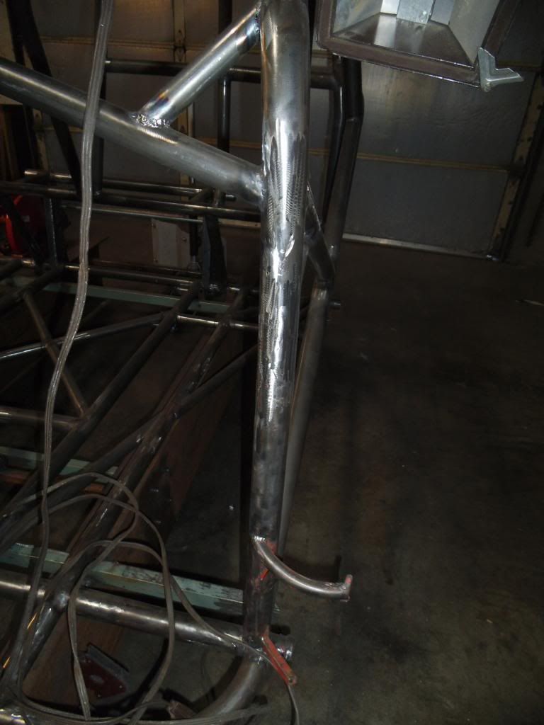
Armed with the CAD drawing I was able to locate and sand down all of the spots on the main tubes where there would be welds (much easier while I could tip up the chassis), then started cutting and notching the tubes for the main floor pieces.
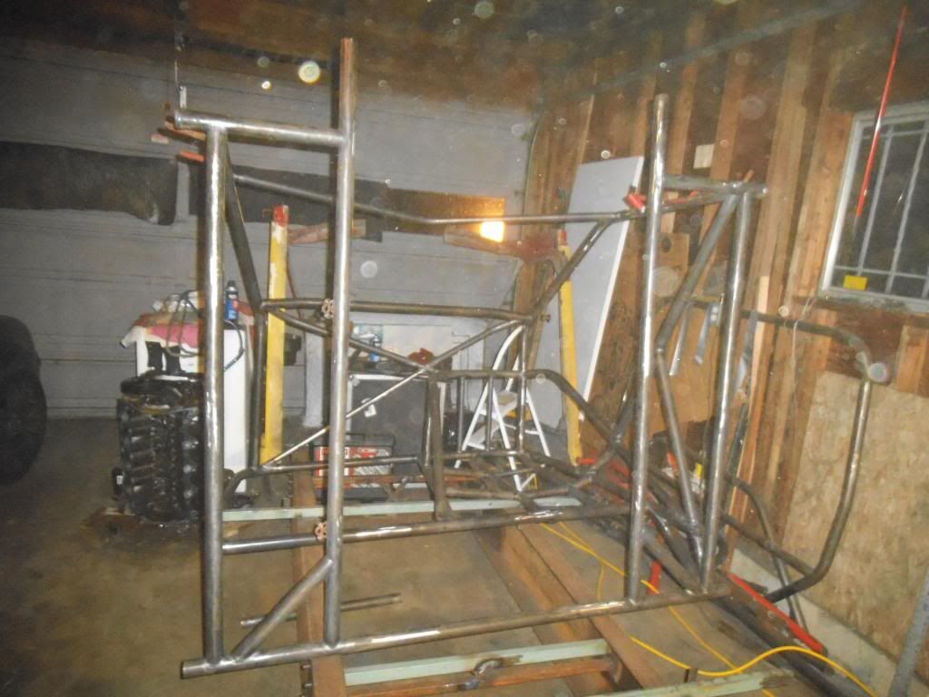
Yes, it looks like it's snowing or smoky in my garage from all the crap in the air from the metal prep work. After seeing that photo I decided to go back to using a respirator when doing that type of work!
Another thing you learn quickly about TIG welding is that the tubing needs to be REALLY clean both inside and out at every joint. When I started this work I was only cleaning as much as I used to do with MIG welding on mild steel, and the result was a weld puddle that snapped, crackled and popped like Rice Crispies on steroids. Now I use lots of carb cleaner to degrease, then a sanding disc on an angle grinder, plus a sanding roll on a die grinder to clean up the inside, then a final cleaning with carb cleaner. I make sure to NEVER use brake-cleaner, as some blends include chemicals that will turn into poisonous gas when exposed to heat.
I have now received written "blessing" from the NHRA on the photos of the previously disputed areas, as well as my CAD drawings of the remaining fabrication before the chassis certification (which should happen in just over a week when the certification tech comes to our local track). It's tough to get a lot of work done while still spending "quality time" with my daughter (and she's going through a "girlie girl" phase where she doesn't want to get dirty in the garage), so I've been mostly working after 9:30 pm and between 4:00 am and 6:30 am. I do my best to always keep the doors closed when doing something noisy, but my neighbors probably still hate me!
One thing I forgot to add to the last update: I hadn't driven the MBRP Dirtymax in a while as I was working on this truck, but the opportunity came up to drive it at the last 2 events of 2012. We ended up winning the World Championship in NHRDA Pro Stock!

The coolest thing is that over 40 million viewers tuned in to watch the event on Fox Sports Net! While that's great for the sport, I have to remember that it's probably a small fraction of the people who watch Honey Boo Boo (and no, I never have)...
A couple more sponsorship-related items:
Would you please "Like" our ISSPRO facebook page? It will help show the bosses that sponsoring this truck is a good thing! http://www.facebook.com/IssproInc
We are happy to announce that Mahle has signed on as an Associate Sponsor, and we will be running Mahle pistons in the truck. Don't tell them, but even without sponsorship help I would have gotten their pistons anyway
After all that excitement it was back to the garage! As I started finish-welding some of the junctions of several tubes, I found that I had to extend the TIG torch's electrode so far out that I didn't get good shielding gas coverage. I had planned to pick up a "gas lens" for the torch, which is something that focuses the flow into a nice even column of gas. I ended up getting a specific version of the gas lens called a CK Gas Saver, which is designed to work well at reduced argon flow rates (saving some money in the process). It was also cool that its cup for the shielding gas is a clear pyrex-type glass, giving better visibility of the arc and puddle.

I tried it out and it was awesome! Unfortunately it was also breakable, and I set the torch down on the jig to grab more filler rod, and it slid off and broke! I ordered some spare parts and got it back together. This thing would have already paid for itself in reduced gas costs, had I started using it at the start of the project. Heck, it is worth it in reduced blood pressure from trying to make some of those long-reach welds work!!!
Next up I installed the "X" braces across the roof of the cage. The corner mounting points resulted in some weird complex angles, so the tube end fitting was difficult and cumbersome (but then again what HASN'T been on this build???).

One item on tube fitting that is worth mentioning: when you use a notcher to cut the contour in the mating tube, the farthest forward edges end up downright sharp.

As I discovered early on, if you don't "blunt" those edges with a grinder, you end up with a very thin section when you weld, and if the weld puddle is at the edge of the tubing you will end up with a hole as the thin section melts away. By blunting the edges you move the weld location to where the tubing is full thickness.

I decided to go ahead and flip the chassis over and get at all the weld spots I had skipped to this point. Once I add the front of the chassis it will be a lot harder to flip and maneuver in my little garage!

I removed a diagonal from the firewall area, as that section will be extended to give me more room for the pedals. It was nice to have my plasma cutter working well again, having replaced a worn out electrode!

With that diagonal out of the way, I found that the section of the original floor had a twist to it, and needed a little "persuasion" to get it flat:

I added a new crossmember and alignment tabs for holding the front frame rails into the jig.


One of the things I am trying to do is come up with quicker ways of doing some of the repeated tasks in this build. One of those tasks is cutting small strips or plates of metal, either for the jig or for brackets on the chassis. When I built my gasser chassis many years ago I borrowed a Whitney shear and punch from my family business, which allows me to make short work of many of those tasks. I went ahead and found used versions of the same tools on ebay to use for this build.

As I started laying out the details of the floor area, I decided it was worth it to lay it out in CAD so I had a better starting point for the measurements and angles of the tubes I was going to be cutting and notching. I was hoping to do this in a solid CAD model, but I hadn't touched a solid/3D CAD program in MANY years! I had been using a freeware 2D program for the last several years to do simple stuff like laying out the rear frame of my small block Vega, and designing the parachute mount for my big block Vega. I found a decent solid modeling program with a free demo, but was still learning it and decided to just get it done in the 2D program I was familiar with:

I discovered that the freeware version didn't allow angular dimensioning, but the "Pro" version was only $37.50, and I've gotten waaay more utility out of their package than that over the years!
As with the prior spreadsheet I had used to organize the tubes I needed, this would help me optimize the cuts so I could get the most usable tubing out of the lengths I had. Plus it was something to do while thawing my toes on the really cold mornings of working on this chassis! The drawing would also help me figure out which tubes had to go in a specific order, to avoid "painting myself into a corner" like I did in the funny car cage area. With the larger diameter tubes that make up the main floor bars, the ratchet strap trick might not work!
Armed with the CAD drawing I was able to locate and sand down all of the spots on the main tubes where there would be welds (much easier while I could tip up the chassis), then started cutting and notching the tubes for the main floor pieces.

Yes, it looks like it's snowing or smoky in my garage from all the crap in the air from the metal prep work. After seeing that photo I decided to go back to using a respirator when doing that type of work!
Another thing you learn quickly about TIG welding is that the tubing needs to be REALLY clean both inside and out at every joint. When I started this work I was only cleaning as much as I used to do with MIG welding on mild steel, and the result was a weld puddle that snapped, crackled and popped like Rice Crispies on steroids. Now I use lots of carb cleaner to degrease, then a sanding disc on an angle grinder, plus a sanding roll on a die grinder to clean up the inside, then a final cleaning with carb cleaner. I make sure to NEVER use brake-cleaner, as some blends include chemicals that will turn into poisonous gas when exposed to heat.
I have now received written "blessing" from the NHRA on the photos of the previously disputed areas, as well as my CAD drawings of the remaining fabrication before the chassis certification (which should happen in just over a week when the certification tech comes to our local track). It's tough to get a lot of work done while still spending "quality time" with my daughter (and she's going through a "girlie girl" phase where she doesn't want to get dirty in the garage), so I've been mostly working after 9:30 pm and between 4:00 am and 6:30 am. I do my best to always keep the doors closed when doing something noisy, but my neighbors probably still hate me!


