This will be a continuation of the thread where we dissect the failed LLY FICM. https://www.duramaxdiesels.com/forum/threads/lly-ficm.89101/
This one was graciously loaned to me by Brad (Bdsankey) (to look over and see if there are any worthwhile capacitor upgrades or other modifications that could help increase the life of these aging units.
Good news is, there may not be any reason on the ones for the LB7 to change anything as these seem to be built with a much better overhead then the LLY ones. The two injector driver capacitors are film capacitors by TDK. A premium Japanese electronics manufacturer. Good stuff. Interestingly they are only rated at 100 volts. But being that it is being used on regulated DC it's chance of seeing voltage spikes is likely zero. The LB7 uses 96 volt injectors so it is close to the capacitor rating but being a film capacitor they are known for their long life and low failure rate. When they do fail it's typical to be a soft fail where it doesn't blow up, short or discharge it's electrolyte. It just goes open and stops being a capacitor. This is good.
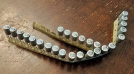
In the LLY it uses electrolytic capacitors for the injectors. These have shorter life as the electrolyte can dry out, it can fail by shorting or overheating and dumping it's electrolyte all over the circuit board and possibly shorting the board out destroying other components. The use of film capacitors in the LB7 is definitely preferred.
The regulation circuit for the rest of the board, chips and other electronics does use the standard electrolytic capacitors. But they also over rated them by quite a lot. Even if they operated at the alternator voltage of 14.2 volts or so, the 50 volt rating of the capacitors gives it a lot of overhead. In contrast the LLY uses 14 volt capacitors. Which is a bit of a heat scratcher as that doesn't have any overhead. In fact it would be continuously operating at just over it's rating which would shorten it's life considerably over one that ran about mid range of it's voltage rating. Bean counters getting in the way???
Ok, some photos

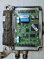
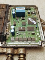
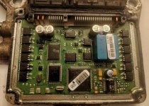
The blue rectangle "boxes" are these film capacitors I've been telling you about. These are 15 uf 100 volt. The blue cylinders are the electrolytic capacitors and are 180 uf and 50 volts. I would not be surprised if there was two independent regulators for the on board chips due to the two separate layouts of the capacitors. The LLY only has one since they are all connected together in parallel

Another interesting note is the injector driver mosfets. These are the switches that turn on and off each injector. These are placed in the row of components at the top and bottom of the board. The last four of the top right and last four bottom left. That is eight total for one per an injector. If you take a look at the other thread of the LLY FICM you'll notice that the LB7 driver mosfets are larger then the LLY's. Assuming it takes the same, or close to it, wattage to operate the LLY's and LB7's injectors, and with the LLY operating at half the voltage (48 volts) that would mean double the current. While it's possible the mosfets are rated the same or well within the operating range, the LB7 mosfets being considerably larger would allow for better heat dissipation. And lower thermal stress.
From what I see here, I would not recommend any changes unless someone has one that failed and we can open it up to see what went wrong
This one was graciously loaned to me by Brad (Bdsankey) (to look over and see if there are any worthwhile capacitor upgrades or other modifications that could help increase the life of these aging units.
Good news is, there may not be any reason on the ones for the LB7 to change anything as these seem to be built with a much better overhead then the LLY ones. The two injector driver capacitors are film capacitors by TDK. A premium Japanese electronics manufacturer. Good stuff. Interestingly they are only rated at 100 volts. But being that it is being used on regulated DC it's chance of seeing voltage spikes is likely zero. The LB7 uses 96 volt injectors so it is close to the capacitor rating but being a film capacitor they are known for their long life and low failure rate. When they do fail it's typical to be a soft fail where it doesn't blow up, short or discharge it's electrolyte. It just goes open and stops being a capacitor. This is good.
In the LLY it uses electrolytic capacitors for the injectors. These have shorter life as the electrolyte can dry out, it can fail by shorting or overheating and dumping it's electrolyte all over the circuit board and possibly shorting the board out destroying other components. The use of film capacitors in the LB7 is definitely preferred.
The regulation circuit for the rest of the board, chips and other electronics does use the standard electrolytic capacitors. But they also over rated them by quite a lot. Even if they operated at the alternator voltage of 14.2 volts or so, the 50 volt rating of the capacitors gives it a lot of overhead. In contrast the LLY uses 14 volt capacitors. Which is a bit of a heat scratcher as that doesn't have any overhead. In fact it would be continuously operating at just over it's rating which would shorten it's life considerably over one that ran about mid range of it's voltage rating. Bean counters getting in the way???
Ok, some photos

The blue rectangle "boxes" are these film capacitors I've been telling you about. These are 15 uf 100 volt. The blue cylinders are the electrolytic capacitors and are 180 uf and 50 volts. I would not be surprised if there was two independent regulators for the on board chips due to the two separate layouts of the capacitors. The LLY only has one since they are all connected together in parallel

Another interesting note is the injector driver mosfets. These are the switches that turn on and off each injector. These are placed in the row of components at the top and bottom of the board. The last four of the top right and last four bottom left. That is eight total for one per an injector. If you take a look at the other thread of the LLY FICM you'll notice that the LB7 driver mosfets are larger then the LLY's. Assuming it takes the same, or close to it, wattage to operate the LLY's and LB7's injectors, and with the LLY operating at half the voltage (48 volts) that would mean double the current. While it's possible the mosfets are rated the same or well within the operating range, the LB7 mosfets being considerably larger would allow for better heat dissipation. And lower thermal stress.
From what I see here, I would not recommend any changes unless someone has one that failed and we can open it up to see what went wrong
Last edited:


