Engineers?

McRat

Diesel Hotrodder
Aug 2, 2006
11,249
26
38
64
Norco CA
www.mcratracing.com
If there are any mechanical engineers in here, I need some help.
I have a splined shaft, that is 1.083" major OD, and has 25 teeth.

I'm thinking it must be metric, with a 26mm pitch dia?

Anyone familiar with involute splines?

Trying to locate an external spline for it.
 

btfarm

you know
Nov 25, 2010
387
0
0
Sandwich, Illinois
I'll have to go dig deeper tomorrow unless somebody else comes up with something.
What would help in finding the right data is application info (what is it used for), root diameter and tooth width at root and crown (so we can find pressure angle).
 

btfarm

you know
Nov 25, 2010
387
0
0
Sandwich, Illinois
It's an electric motor output shaft, and it's custom made.
That tells me there is no sliding motion. Only rotary. Now I REALLY need to have the root dia, root width, crown width and since it's custom I'd like to know if the roots look flat or curved. Common splines are flat root, side fit but this application may be 'uncommon';).
 

mill1901

Newb
Nov 6, 2012
10
0
1
Thief River Falls, MN
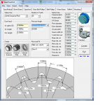
It looks like it's SI. I used a program called GearTrax with the information you listed to create the splines in SolidWorks. The actual outer diameter of the gear is 1.0833 inches, this gives a pitch diameter of 1.0417 inches. Below is a screen shot of GearTrax with your splines in it, a SolidWorks part, and a SolidWorks drawing.
 

Attachments

  • geartrax.png
    geartrax.png
    229 KB · Views: 49
  • splines drawing.png
    splines drawing.png
    48.9 KB · Views: 37
  • splines.png
    splines.png
    284.1 KB · Views: 41

btfarm

you know
Nov 25, 2010
387
0
0
Sandwich, Illinois
That's a nice tool. Inventor doesn't get that far and I didn't have time to calculate the old fashoined way like I was going to do tomorrow with the additional info if he provides it. I'll still take a look if I can tomorrow afternoon.
 

Slammed2007Lbz

Super Spicy Tunaz
Feb 1, 2009
1,118
0
36
NE Ohio
I just wanted to say this thread is way beyond my mental capacity:roflmao: Fun to know that you guys know your shit though:thumb:
 

lts1ow

Needs moar PAH!
May 14, 2012
1,598
0
36
NJ
Any more info on the gear trax program?

I usually just fudge the spline for the model/drawing and have correct callout for machinist in table.
 

DURAMXD

BOB SAGET!
Apr 24, 2012
348
0
16
Wichita, KS
Wow, that GearTrax program is pretty slick. Is it just outputting the gear cross section drawing and then you're just modeling in SW? Or will it output a .prt or .igs file or something?

I was going to bust out my machine design books and try to help, but these are much better answers. I haven't messed with gear design since school, I just build big airplanes now.
 

McRat

Diesel Hotrodder
Aug 2, 2006
11,249
26
38
64
Norco CA
www.mcratracing.com
Somebody break out the Machinery's Handbook and look up the spline. Mine's at home right now.

There are no tables for common fine splines like you find on shafts, just formulas to generate new shafts.

I have a hunch I'm going to have just machine the spline off and go keyed output. Unless I can find a non-custom source for an internal mating part. I can't make internal splines.
 

mill1901

Newb
Nov 6, 2012
10
0
1
Thief River Falls, MN
Wow, that GearTrax program is pretty slick. Is it just outputting the gear cross section drawing and then you're just modeling in SW? Or will it output a .prt or .igs file or something?

I was going to bust out my machine design books and try to help, but these are much better answers. I haven't messed with gear design since school, I just build big airplanes now.

GearTrax creates it's own file .gtx you can choose to create the part is SW and geartrax will build it for you, I did not change it at all in SW. There are options in geartrax to change the length/width of the gear and what type of attachment you want whether it's a hub or keyed.