2005 lly duramax map sensor/wiring issue

flyinwrenches

Member
Jun 13, 2024
35
7
8
Oklahoma
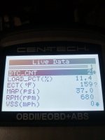
Hey guys, I am working on a truck for a guy and it's a 2005 lly. It kept blowing off the y bridge elbow, because it had a cheap egr delete on it. I order the y bridge strap from pro fab and put on for him. That fixed the blowing off issue, but I noticed it was way over boosting. (Probably why it kept blowing the elbow off). I pulled up the live data and noticed the map was at 4.5 psi all the time. I checked the sensor and noticed that the plug was broke off. So, I bought a new sensor and installed it (skp brand). Now, at idle or wot it reads 37 psi all the time. No change, no boost, no turbo sweep and no power. So, I disconnected the wiring connector and probed across from the 5v ref to low ref on the connector and got a solid 5.06 volts. That would mean the ground and 5v ref is good I assume. That can only mean it's a bad map sensor, right? Another thing I wonder is if they sold me the barometric sensor instead of the map. However, the parts guy insisted that either one would work for the map. Anyways, if I have 5v ref and solid ground, then it has to be a faulty part, right? Or am I missing something? Gm wants 180 bucks for their Ac Delco brand. I have already placed an order at the dealer for one, but if it don't fix it, then I have wasted some money. Could it still be a problem in the wiring?

Edit- also, I forgot to ask, someone said you should change the barometric sensor with the map as a set. Is that true? If the baro sensor is still good, why does it have to be changed? I could see if it was a programmable part, but they aren't as far as I know.
 
Last edited:

2004LB7

Super Moderator
Staff member
Dec 15, 2010
7,108
2,213
113
Norcal
I wouldn't make any assumptions that the ground and 5v are good and it has to be the sensor. What does it read unplugged? Did you ohm out all the lines and check ohms between the lines too?

Screenshot_20240926-173658~01~01.jpg

Screenshot_20240926-173528~01.jpg
 
  • Like
Reactions: flyinwrenches

flyinwrenches

Member
Jun 13, 2024
35
7
8
Oklahoma
I wouldn't make any assumptions that the ground and 5v are good and it has to be the sensor. What does it read unplugged? Did you ohm out all the lines and check ohms between the lines too?

View attachment 126160

View attachment 126161
I did not ohm the wires. Unplugged it is still reading 4.5psi on live data. Plugged in it goes up to 37psi. Are you thinking the signal wire is shorted to ground? That was my thought. If the 5v ref or the low ref was shorted to ground or power, then it would be reading less than 5 or more than 5v on one and the ref wire wouldn't matter as much if it was grounded but if it was shorted to power, then it wouldn't work as ground to read 5v. However, if the signal wire was grounded, it might overwhelm the map resistor into a false reading....maybe??
 
Last edited:

flyinwrenches

Member
Jun 13, 2024
35
7
8
Oklahoma
I will ohm them tommorow and check the continuity. If I understand the working principle of the map, the signal wire should read a amperage drop through the resistor and send that to the ecm, which is programmed to a "value conversion" that takes the Amp reading and translates it to psi or gm/s. So, a direct short to ground would make it max value, because no amps would reach the ecm. With no boost, the resistance across the 5v would be negligible, which would make its psi translation low. However, a direct short to ground on the 5v would cause it to "default" to set parameters. Right? So, high impedance on the signal wire would be all it could be, or a bad map with a incorrect resistance. Right? Please correct me if I am understanding it wrong. Thanks!
 
Last edited:

flyinwrenches

Member
Jun 13, 2024
35
7
8
Oklahoma
Of course, the map probably wouldn't read 0 unplugged if the ecm senses a open circuit and switches to default setting to keep it going...right? However, I don't know what the programmed default reading for a map sensor would be.
 

flyinwrenches

Member
Jun 13, 2024
35
7
8
Oklahoma
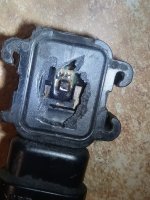
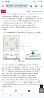
This is what it looks like inside...for anyone curious.
 

Attachments

  • 20240926_210030.jpg
    20240926_210030.jpg
    405.5 KB · Views: 8
  • Screenshot_20240926_211214_Chrome.jpg
    Screenshot_20240926_211214_Chrome.jpg
    343.4 KB · Views: 7

2004LB7

Super Moderator
Staff member
Dec 15, 2010
7,108
2,213
113
Norcal
I will ohm them tommorow and check the continuity. If I understand the working principle of the map, the signal wire should read a amperage drop through the resistor and send that to the ecm, which is programmed to a "value conversion" that takes the Amp reading and translates it to psi or gm/s. So, a direct short to ground would make it max value, because no amps would reach the ecm. With no boost, the resistance across the 5v would be negligible, which would make its psi translation low. However, a direct short to ground on the 5v would cause it to "default" to set parameters. Right? So, high impedance on the signal wire would be all it could be, or a bad map with a incorrect resistance. Right? Please correct me if I am understanding it wrong. Thanks!
Close. Replace amps with volts and you get closer. Many of these sensors are just voltage dividers. Some are frequency based that output a specific frequency for a detected flow or pressure. But based on what I see on the schematic I posted above it looks like a voltage divider. 5v on one side, ground on the other and the signal sweeps between them with a varying voltage.

Typically if the signal is lost then it defaults to the lowest value in the table. If it shorts to the 5v then it maxes out. Moisture or bad connection, corrosion, etc can create an in-between condition or one that is unreliable. So an ohm test through the line plus between the lines is always a good idea. It's also recommended to load test them too as frayed, damaged and corroded wires can sometimes read good with a DVM but fail under load. A turn signal or break light bulb makes a good load tester

If it's a direct short to ground or 5v then there will almost always be an associated code. But if it's intermittent, or frayed, damaged or corroded then it may not

If it all checks out then try a sensor. It it still has issues then take a close look at the pins on the ECM and sensor side. If all else fails then suspect the ECM. But rule out all the above first
 
  • Like
Reactions: flyinwrenches

flyinwrenches

Member
Jun 13, 2024
35
7
8
Oklahoma
Close. Replace amps with volts and you get closer. Many of these sensors are just voltage dividers. Some are frequency based that output a specific frequency for a detected flow or pressure. But based on what I see on the schematic I posted above it looks like a voltage divider. 5v on one side, ground on the other and the signal sweeps between them with a varying voltage.

Typically if the signal is lost then it defaults to the lowest value in the table. If it shorts to the 5v then it maxes out. Moisture or bad connection, corrosion, etc can create an in-between condition or one that is unreliable. So an ohm test through the line plus between the lines is always a good idea. It's also recommended to load test them too as frayed, damaged and corroded wires can sometimes read good with a DVM but fail under load. A turn signal or break light bulb makes a good load tester

If it's a direct short to ground or 5v then there will almost always be an associated code. But if it's intermittent, or frayed, damaged or corroded then it may not

If it all checks out then try a sensor. It it still has issues then take a close look at the pins on the ECM and sensor side. If all else fails then suspect the ECM. But rule out all the above first
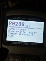
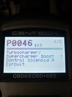
Ok, good info. So, what would be a maxed out psi on the live data? I read 37 psi regardless of engine load or rpm fluctuations. If I disconnect the connector, the reading drops to 4.5 psi. If 37 is the max, then does that mean the signal wire is maxed out to 5v? Here is the associated codes and map reading.
 

Attachments

  • 20240925_201916.jpg
    20240925_201916.jpg
    171 KB · Views: 4
  • 20240925_201923.jpg
    20240925_201923.jpg
    175.9 KB · Views: 3
  • 20240925_202006.jpg
    20240925_202006.jpg
    189 KB · Views: 3

flyinwrenches

Member
Jun 13, 2024
35
7
8
Oklahoma
I would guess the sensor is bad and sending 5v down the signal wire. But I wouldn't skip testing the wires
Ok, I will check the wires thoroughly tommorow. I sure appreciate your advise, help and info. This is an awesome forum. There's a lot more technical knowledge and info here than some other forums. Again, thanks!
 
  • Like
Reactions: 2004LB7

2004LB7

Super Moderator
Staff member
Dec 15, 2010
7,108
2,213
113
Norcal
Is there a specific value for this ohm test? Published somewhere?
If you are just measuring the wires, end to end should be as close to zero ohms as possible. Most meters don't have the resolution needed to accurately measure values that low so as long as it's sub 1 ohm your probably fine. Load testing is a way to confirm integrity too. For wire to wire or cross contamination, shorts, etc between conductors or ground, you want as high resistance as possible. Most meters should display OL or "open line" or in other words higher then what the meter is capable of measuring.

So, ideally you want zero ohms from one wire end to end and infinite ohms between another wire to another

The only resistance or current flow should be through the sensor, switch or load that is plugged in to the connector on the end. Nothing should bypass this
 
  • Like
Reactions: Ron Nielson

flyinwrenches

Member
Jun 13, 2024
35
7
8
Oklahoma
The guy needed his truck back to drive it a couple days this weekend. So, he took it today. I didn't get a chance to finish it. I will test the wires when he brings it back. I told him it wasn't going to build any boost or have much power. Hopefully it don't tear it up driving it a little with a bad map problem. I know it will be running lean and have little boost. I am worried about it tearing anything up. It probably won't, will it? I mean, I could have left it as unplugged to make it read default values all the time, but I figured then it would overboost and overfuel. So, it is a losing situation either way. Of course, with the map connection broken when it came in, it was running on default values before. But I figured that was even harder on it. He is bringing it back Monday.
 

2004LB7

Super Moderator
Staff member
Dec 15, 2010
7,108
2,213
113
Norcal
Lean conditions wont hurt anything. Only over fueling or excessive timing will. As least for what you are concerned with. If it's weak or low on power and running lean then let him drive it all he wants.

Remember, this is a diesel and not gasoline. Apple and Orange when it comes to fuel to air ratios and timing. Little carries over between them
 
  • Like
Reactions: flyinwrenches