Limp mode
- Thread starter 2015 lml 3500 dually
- Start date
You are using an out of date browser. It may not display this or other websites correctly.
You should upgrade or use an alternative browser.
You should upgrade or use an alternative browser.

which cables? Which exactly should I check?Have you ohmed out the wires yet?
Today I removed all the tape from the cables on the passenger side, removed. cleaned and reinstalled the ground wire in the chassis, cleared the codes and all is still the same
I did not chek the ohms but if the voltage for example in the maf connector pin A 0 volt, pin B 12.68 volt, pin C 5.3 volt, pin D 5.3 volt. Pin E 0 volt
can someone please fix it? i'm in louisville kentucky but i can move some state near me, indiana, chicago, tennessee, Ohio?
P0113
The IAT Sensor 1 parameter is colder than -39°C (-38°F) for greater than 1 second. This is equal to greater than 4.8 volts on the IAT signal circuit as measured by the ECM.
Action Taken When the DTC Sets
DTC P0112 and P0113 are Type B DTCs.
Conditions for Clearing the DTC
DTC P0112 and P0113 are Type B DTCs.
Diagnostic Aids
With the ignition ON and the engine OFF, if the engine is cold, a properly functioning IAT sensor will gradually increase the scan tool IAT Sensor parameter. This is due to the heat that is generated by the mass air flow (MAF) sensor heating elements.
Depending on the ambient temperature, an IAT sensor signal circuit or low reference circuit that is shorted to the MAF sensor signal circuit can cause a DTC P0113 to set. This condition can cause a rapid fluctuation in the IAT Sensor parameter.
An IAT low reference circuit that is open can cause the IAT Sensor parameter response to be sluggish. This condition may not necessarily set a DTC.
An IAT sensor signal circuit that is shorted to the MAF sensor ignition circuit can cause a DTC P0113 to set.
Verify that any electrical aftermarket devices are properly connected and grounded. Refer to Checking Aftermarket Accessories. See: Testing and Inspection\Component Tests and General Diagnostics
Circuit/System Verification
Engine running, observe the scan tool IAT Sensor 1 parameter. The reading should be between -38 to +148°C (-36 to +298°F) depending on the current ambient temperature and the vehicle operating conditions.
Operate the vehicle within the Conditions for Running the DTC. You may also operate the vehicle within the conditions that you observed from the Freeze Frame/Failure Records data.
Circuit/System Testing
Ignition OFF, disconnect the harness connector at the mass air flow MAF/IAT sensor.
Ignition OFF, for 90 seconds, test for less than 5 ohms between the IAT Sensor 1 low reference circuit terminal 4 and ground.
If greater than the specified range, test the IAT Sensor 1 low reference circuit for an open/high resistance. If the circuit tests normal, replace the ECM.
Ignition OFF, test for less than 5 ohms between the MAF sensor low reference circuit terminal 2 and ground.
If greater than the specified range, test the MAF sensor low reference circuit for an open/high resistance. If the circuit tests normal, replace the ECM.
Ignition ON, verify the scan tool IAT Sensor 1 parameter is less than -39°C (-38°F).
If warmer than the specified range, test the signal circuit terminal 5 for a short to ground. If the circuit tests normal, replace the ECM.
Install a 3A fused jumper wire between the signal circuit terminal 5 and a ground. Verify the scan tool IAT Sensor 1 parameter is warmer than 148°C (298°F).
If colder than the specified range, test the signal circuit for a short to voltage or an open/high resistance. If the circuit tests normal, replace the ECM.
If all circuits test normal, test or replace the MAF/IAT sensor.
08lmm72mm Thank you. Good information, now 3 rainy days are coming and I don't have a garage, as soon as I can within my poor knowledge I will try to check

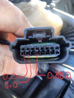
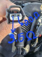

This are the results I got, I really don't kknow if it is correct, someone else has any ideas, I'd attach some pictures too.