LLY Ficm

2004LB7

Well-known member
Dec 15, 2010
6,982
2,145
113
Norcal
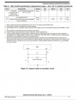
Anyone able to give pointers for using an external resonator/oscillator for the above mentioned processor (NXP Semicon S9KEAZN64AMLH)? Or if it is even needed? Can't figure out the capacitor sizing for the crystal. Or really what frequency it should be running at. I assume there is an optimal frequency that would work best with the serial communication baud rate. Haven't had to deal with this part before so I'm a little behind the curve

Also, programming pins. Do these just use the same RX/TX or is there others? Can't seem to find much for programming ARM processors. Most datasheets, documents and discussions seems to revolve around the code more then the actual physical pins and requirements for hardware. Would be nice to route the appropriate pins to the connector so it can be bench programmed without having to open it up each and every time

Screenshot_20231031-082528~01.jpg
 

Attachments

  • S9KEA64P64M20SF0-1274920.pdf
    799 KB · Views: 2

2004LB7

Well-known member
Dec 15, 2010
6,982
2,145
113
Norcal
Rx Tx should directly go to USB If same NXP layout I use. Will share schematics for my clock and programing port later today.

Sent from my SM-S901U using Tapatalk
Awesome. Also I think this chip has the CAN translator built in so it seems like we should be able to run the J1939 right into it. Is that what you see? It also appears to have up to 5 pairs of RX/TX available with one being labeled with CAN. So would we use one for USB and the CAN set for the J1939?

If we don't need the dedicated CAN translator then it also removes the need for the 3.3v regulator, associated components and wires. This cleaning up the board even more
 

2004LB7

Well-known member
Dec 15, 2010
6,982
2,145
113
Norcal
Another question. For the LB7 and LLY voltage difference, I would use a voltage divider to drop the 12v down to 4.8v to be able to feed that into the chip. Normally I was thinking that I would turn that voltage divider off for use on the LLY's 5v signal. But if I leave it in place without turning it on or off, the 5v would be dropped to about 2 volts. I assume this is plenty for the chip to be able to register the signal properly. If so then that would eliminate the chance of accidentally having the divider off and plugging it into an LB7 and killing the chip.

Bit now that I think about it, the Opto-isolators should be able to deal with that. Just feed the 5v on the control side and the signal, wether it be 5 or 12 volts should always be 5 on the output to the processor
 

kidturbo

Piston Tester
Jul 21, 2010
2,539
1,375
113
Somewhere On The Ohio
www.marinemods.us
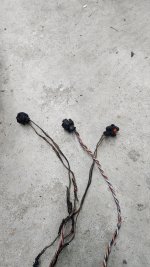
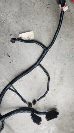
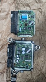
Repaired the old LLY boat harness this week. It was a bit crispy on the right bank when I cut it open. Melted injector 3, 5, and 7 injector leads together, and the connector off #1. So I was concerned with the FICM being damaged. Jason suggested I inspect the caps, and figured would be a good chance to show the LB7 and LLY boards side by side for comparison.

20231119_234002.jpg 20231119_233607.jpg

20231120_152522.jpg

After physical inspection, I ran it on the emulator for a couple minutes, at 5000rpm.. PASS :D
 

Attachments

  • 20231119_233607.jpg
    20231119_233607.jpg
    464.4 KB · Views: 17

PureHybrid

Isuzu Shakes IT
Feb 15, 2012
3,494
474
83
Central OH
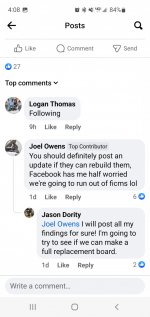
There's been a few guys on the book of faces that are supposedly going to try and make a replacement board, if they can't repair all these burnt ones that others are sending to them.
 

1FastBrick

Well-known member
Dec 1, 2016
2,541
1,069
113
Junkyard
Guess now we need to delete all 700 pictures and diagrams....
Ah wait,, I forgot that at least 600 of those posts are just my meaningless rants/// :D

If it was easy, bigger dogs would have done it already.. GM even outsourced this job, to Bosch.
At least the Screen Shots of the captured data and other useful information...
 
  • Like
Reactions: 2004LB7