Info: 2001 GMC Wiring Diagram Needed
- Thread starter WisconsinHick1
- Start date
You are using an out of date browser. It may not display this or other websites correctly.
You should upgrade or use an alternative browser.
You should upgrade or use an alternative browser.

Junction Block - Underhood C2


Connector Part Information
Wire Color
Circuit No.
Function
A1–A2
—
—
Not Used
A3
DK BLU
604
A/C High Pressure Recirculation Switch Signal
A4–A7
—
—
Not Used
A8
ORN
440
Battery Positive Voltage
A9
LT GRN
24
Backup Lamp Supply Voltage
A10
LT BLU
1320
CHMSL Supply Voltage
A11
GRY/BLK
2219
FICM Relay Control
A12
—
—
Not Used
B1–B2
—
—
Not Used
B3
DK GRN
59
A/C Compressor Clutch Supply Voltage
B4
—
—
Not Used
B5
LT BLU
203
A/C Request Signal
B6
PNK
239
Ignition 1 Voltage
B7
DK GRN/WHT
465
Fuel Pump Relay Control [- Primary]
B8
ORN
440
Battery Positive Voltage
ORN
440
Battery Positive Voltage
B9
PNK
1339
Ignition 1 Voltage
B10–B12
—
—
Not Used
C1–C3
—
—
Not Used
C4
PNK
239
Ignition 1 Voltage
C5–C9
—
—
Not Used
C10
PNK
1039
Ignition 1 Voltage
PNK
1039
Ignition 1 Voltage
C11
PNK
439
Ignition 1 Voltage
PNK
1039
Ignition 1 Voltage (Diesel)
C12
PNK
1239
Ignition 1 Voltage
PNK
1239
Ignition 1 Voltage
D1
BLK/WHT
1695
Axle Switch Signal
D2
—
—
Not Used
D3
DK GRN/WHT
459
A/C Clutch Relay Control
D4–D7
—
—
Not Used
D8
PNK
539
Ignition 1 Voltage
PNK
539
Ignition 1 Voltage
D9
PNK
639
Ignition 1 Voltage
D10
PNK
1039
Ignition 1 Voltage
PNK
1039
Ignition 1 Voltage
D11
PPL
6
Starter Solenoid Crank Voltage
D12
BLK
550
Ground
E1
BLK/WHT
1695
Axle Switch Signal
BLK/WHT
1695
Axle Switch Signal
E2
PNK
1020
Off/Run/Crank Voltage
PNK
1020
Off/Run/Crank Voltage
E3
LT GRN
275
Park Neutral Position Switch Park Signal
E4–E5
—
—
Not Used
E6
PNK
1239
Ignition 1 Voltage
E7
PNK
1239
Ignition 1 Voltage
PNK
1239
Ignition 1 Voltage
E8
PNK
1539
Ignition 1 Voltage
PNK
1539
Ignition 1 Voltage
PNK
439
Ignition 1 Voltage (Diesel)
E9–E11
—
—
Not Used
E12
PNK
1039
Ignition 1 Voltage
F1
—
—
Not Used
F2
PNK
1020
Off/Run/Crank Voltage
PNK
1020
Off/Run/Crank Voltage
F3
LT GRN/BLK
584
A/T Shift Lock Control Switch Supply Voltage
F4
ORN
3440
Battery Positive Voltage
F5
—
—
Not Used
F6
BLK/WHT
451
Ground
F7
BLK
550
Ground
F8
—
—
Not Used
F9
PNK
839
Ignition 1 Voltage
F10
PPL/WHT
1035
Starter Relay Coil Supply Voltage
F11
PPL/WHT
1035
Starter Relay Coil Supply Voltage (M/T)
YEL
1737
Starter Relay Coil Supply Voltage (A/T)
F12
—
—
Not Used
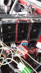
I believe that is connector C2 (black). Hope this helps, I know it's kind of hard to read.
Connector Part Information
- 12193906
- 68-Way F Metri-Pack 280 Series (BLK)
Wire Color
Circuit No.
Function
A1–A2
—
—
Not Used
A3
DK BLU
604
A/C High Pressure Recirculation Switch Signal
A4–A7
—
—
Not Used
A8
ORN
440
Battery Positive Voltage
A9
LT GRN
24
Backup Lamp Supply Voltage
A10
LT BLU
1320
CHMSL Supply Voltage
A11
GRY/BLK
2219
FICM Relay Control
A12
—
—
Not Used
B1–B2
—
—
Not Used
B3
DK GRN
59
A/C Compressor Clutch Supply Voltage
B4
—
—
Not Used
B5
LT BLU
203
A/C Request Signal
B6
PNK
239
Ignition 1 Voltage
B7
DK GRN/WHT
465
Fuel Pump Relay Control [- Primary]
B8
ORN
440
Battery Positive Voltage
ORN
440
Battery Positive Voltage
B9
PNK
1339
Ignition 1 Voltage
B10–B12
—
—
Not Used
C1–C3
—
—
Not Used
C4
PNK
239
Ignition 1 Voltage
C5–C9
—
—
Not Used
C10
PNK
1039
Ignition 1 Voltage
PNK
1039
Ignition 1 Voltage
C11
PNK
439
Ignition 1 Voltage
PNK
1039
Ignition 1 Voltage (Diesel)
C12
PNK
1239
Ignition 1 Voltage
PNK
1239
Ignition 1 Voltage
D1
BLK/WHT
1695
Axle Switch Signal
D2
—
—
Not Used
D3
DK GRN/WHT
459
A/C Clutch Relay Control
D4–D7
—
—
Not Used
D8
PNK
539
Ignition 1 Voltage
PNK
539
Ignition 1 Voltage
D9
PNK
639
Ignition 1 Voltage
D10
PNK
1039
Ignition 1 Voltage
PNK
1039
Ignition 1 Voltage
D11
PPL
6
Starter Solenoid Crank Voltage
D12
BLK
550
Ground
E1
BLK/WHT
1695
Axle Switch Signal
BLK/WHT
1695
Axle Switch Signal
E2
PNK
1020
Off/Run/Crank Voltage
PNK
1020
Off/Run/Crank Voltage
E3
LT GRN
275
Park Neutral Position Switch Park Signal
E4–E5
—
—
Not Used
E6
PNK
1239
Ignition 1 Voltage
E7
PNK
1239
Ignition 1 Voltage
PNK
1239
Ignition 1 Voltage
E8
PNK
1539
Ignition 1 Voltage
PNK
1539
Ignition 1 Voltage
PNK
439
Ignition 1 Voltage (Diesel)
E9–E11
—
—
Not Used
E12
PNK
1039
Ignition 1 Voltage
F1
—
—
Not Used
F2
PNK
1020
Off/Run/Crank Voltage
PNK
1020
Off/Run/Crank Voltage
F3
LT GRN/BLK
584
A/T Shift Lock Control Switch Supply Voltage
F4
ORN
3440
Battery Positive Voltage
F5
—
—
Not Used
F6
BLK/WHT
451
Ground
F7
BLK
550
Ground
F8
—
—
Not Used
F9
PNK
839
Ignition 1 Voltage
F10
PPL/WHT
1035
Starter Relay Coil Supply Voltage
F11
PPL/WHT
1035
Starter Relay Coil Supply Voltage (M/T)
YEL
1737
Starter Relay Coil Supply Voltage (A/T)
F12
—
—
Not Used
I believe that is connector C2 (black). Hope this helps, I know it's kind of hard to read.
Transmission Control Module (TCM) C1

Connector Part Information
Wire Color
Circuit No.
Function
1
BLK/WHT
451
Ground
2
PNK
1020
Off/Run/Crank Voltage
3
ORN
440
Battery Positive Voltage
4
PNK
1020
Off/Run/Crank Voltage
5
BLK/WHT
451
Ground
6
YEL
2522
Power Take Off (PTO) Reference Voltage
7
PPL
420
TCC Brake Switch/ Cruise Control Release Signal
8
—
—
Not Used
9
WHT
2467
Unmanaged Torque Signal
10
GRY/BLK
1694
4WD Low Signal
11–15
—
—
Not Used
16
TAN/BLK
464
Delivered Torque Signal (Gas Only)
17–21
—
—
Not Used
22
ORN/BLK
463
Requested Torque Signal
23–24
—
—
Not Used
25
DK BLU
2687
Transmission MIL Request Signal
26
—
—
Not Used
27
YEL
400
Signal High - Front
28
—
—
Not Used
29
YEL
2361
CAN Data Link Signal HI
30
YEL
2470
Class 2 Serial Data
31
—
—
Not Used
32
DK GRN
2362
CAN Data Link Signal LO
Transmission Control Module C2
Connector Part Information
Wire Color
Circuit No.
Function
1
PNK
1224
Fluid Pressure Switch Signal C
2
DK BLU
1225
Fluid Pressure Switch Signal D
3
RED
1226
Fluid Pressure Switch Signal E
4
LT GRN/BLK
2529
Fluid Pressure Switch Reverse Signal
5
BLK/WHT
771
Transmission Range Switch Signal A
6
YEL
772
Transmission Range Switch Signal B
7
GRY
773
Transmission Range Switch Signal C
8
WHT
776
Transmission Range Switch Signal P
9
—
—
Not Used
10
YEL/BLK
1227
TFT Sensor Signal
11–12
—
—
Not Used
13
ORN
1983
Transmission Turbine Speed Switch Signal
14
LT BLU
1984
Transmission Turbine Speed Switch Low Reference
15
PPL/WHT
821
Vehicle Speed Signal HI
16
LT GRN/BLK
822
Vehicle Speed Signal LO
17
RED/BLK
1230
AT ISS Signal High
18
DK
BLU/WHT
1231
AT ISS Signal Low
19
—
—
Not Used
20
BLK
2762
Low Reference
21
PPL
2471
Trans ID
22
LT BLU/WHT
1229
PPC Solenoid A Valve High Control
23
RED/BLK
1228
PPC Solenoid A Valve Low Control
24
PNK/BLK
2468
PPC Solenoid B Valve High Control
25
BRN/WHT
2469
PPC Solenoid B Valve Low Control
26
LT GRN
1222
Shift Solenoid C Valve Control
27
YEL/BLK
1223
Shift Solenoid D Valve Control
28
ORN/WHT
2527
Shift Solenoid E Valve Control
29
BRN
418
TCC PWM Solenoid Valve Control
30
—
—
Not Used
31
BRN
323
12 Volt Reference
32
DK
GRN/WHT
2528
TCC PWM Solenoid Supply Voltage
Connector Part Information
- 15305371
- 32-Way F Micro-Pack 100W Series (GRY)
Wire Color
Circuit No.
Function
1
BLK/WHT
451
Ground
2
PNK
1020
Off/Run/Crank Voltage
3
ORN
440
Battery Positive Voltage
4
PNK
1020
Off/Run/Crank Voltage
5
BLK/WHT
451
Ground
6
YEL
2522
Power Take Off (PTO) Reference Voltage
7
PPL
420
TCC Brake Switch/ Cruise Control Release Signal
8
—
—
Not Used
9
WHT
2467
Unmanaged Torque Signal
10
GRY/BLK
1694
4WD Low Signal
11–15
—
—
Not Used
16
TAN/BLK
464
Delivered Torque Signal (Gas Only)
17–21
—
—
Not Used
22
ORN/BLK
463
Requested Torque Signal
23–24
—
—
Not Used
25
DK BLU
2687
Transmission MIL Request Signal
26
—
—
Not Used
27
YEL
400
Signal High - Front
28
—
—
Not Used
29
YEL
2361
CAN Data Link Signal HI
30
YEL
2470
Class 2 Serial Data
31
—
—
Not Used
32
DK GRN
2362
CAN Data Link Signal LO
Transmission Control Module C2
Connector Part Information
- 15305371
- 32-Way F Micro-Pack 100W Series (RED)
Wire Color
Circuit No.
Function
1
PNK
1224
Fluid Pressure Switch Signal C
2
DK BLU
1225
Fluid Pressure Switch Signal D
3
RED
1226
Fluid Pressure Switch Signal E
4
LT GRN/BLK
2529
Fluid Pressure Switch Reverse Signal
5
BLK/WHT
771
Transmission Range Switch Signal A
6
YEL
772
Transmission Range Switch Signal B
7
GRY
773
Transmission Range Switch Signal C
8
WHT
776
Transmission Range Switch Signal P
9
—
—
Not Used
10
YEL/BLK
1227
TFT Sensor Signal
11–12
—
—
Not Used
13
ORN
1983
Transmission Turbine Speed Switch Signal
14
LT BLU
1984
Transmission Turbine Speed Switch Low Reference
15
PPL/WHT
821
Vehicle Speed Signal HI
16
LT GRN/BLK
822
Vehicle Speed Signal LO
17
RED/BLK
1230
AT ISS Signal High
18
DK
BLU/WHT
1231
AT ISS Signal Low
19
—
—
Not Used
20
BLK
2762
Low Reference
21
PPL
2471
Trans ID
22
LT BLU/WHT
1229
PPC Solenoid A Valve High Control
23
RED/BLK
1228
PPC Solenoid A Valve Low Control
24
PNK/BLK
2468
PPC Solenoid B Valve High Control
25
BRN/WHT
2469
PPC Solenoid B Valve Low Control
26
LT GRN
1222
Shift Solenoid C Valve Control
27
YEL/BLK
1223
Shift Solenoid D Valve Control
28
ORN/WHT
2527
Shift Solenoid E Valve Control
29
BRN
418
TCC PWM Solenoid Valve Control
30
—
—
Not Used
31
BRN
323
12 Volt Reference
32
DK
GRN/WHT
2528
TCC PWM Solenoid Supply Voltage
This works just fine Ryan I am just putting it into a word document and printing it out thank you again!